


Content
- 1 How an Electric Diaphragm Valve Works
- 2 Weir-Type vs. Straight-Through Body Design
- 3 Key Technical Specifications to Evaluate
- 4 Diaphragm Material Selection: The Most Critical Decision
- 5 Body Materials and Their Application Context
- 6 Fail-Safe Actuation and Power Failure Behavior
- 7 Modulating Control vs. On/Off Operation
- 8 Installation, Commissioning, and Maintenance Considerations
Electric diaphragm valves occupy a specific and important niche in process control and fluid handling engineering — they combine the hygienic, chemically resistant flow isolation characteristics of the diaphragm valve design with the remote actuation, automated control, and feedback capabilities of electric actuation. The result is a valve type that is particularly well suited to applications involving corrosive chemicals, ultra-pure fluids, pharmaceutical and food-grade process media, and any situation where the process fluid must be completely separated from the valve's operating mechanism. Yet despite their wide deployment, electric diaphragm valves are frequently misspecified — the wrong diaphragm material, incorrect actuator torque sizing, or inadequate IP rating for the installation environment are among the most common procurement errors that lead to premature valve failure and process downtime. This article covers how electric diaphragm valves work, what the critical selection parameters are, and how to match the right valve specification to the demands of the specific application.
How an Electric Diaphragm Valve Works
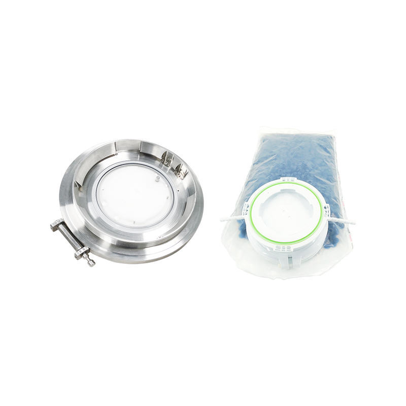
A diaphragm valve controls flow by pressing a flexible membrane — the diaphragm — against a raised weir or saddle in the valve body (weir-type design) or directly onto the valve seat at the base of the flow passage (straight-through design). When the diaphragm is pressed against the weir or seat by the closing mechanism, flow is shut off completely. When the diaphragm is lifted away from the weir, the flow passage opens and fluid passes through. The critical characteristic of this design is that the diaphragm forms the complete boundary between the process fluid and the valve's mechanical operating components — the process fluid never contacts the spindle, packing, actuator, or any part of the operating mechanism above the diaphragm. This separation eliminates the risk of process fluid contamination from valve packing leakage and prevents corrosive or aggressive fluids from attacking the valve's mechanical internals.
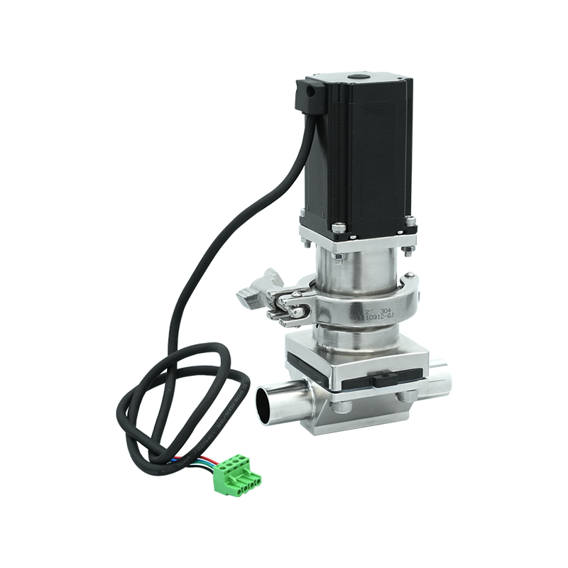
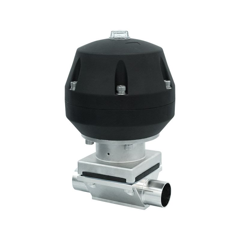
In an electric diaphragm valve, the mechanical force required to depress or lift the diaphragm is provided by an electric actuator rather than a manual handwheel or pneumatic/hydraulic cylinder. The actuator contains an electric motor — typically a DC or AC motor with gear reduction — that drives a lead screw, worm gear, or rack-and-pinion mechanism to produce the linear or rotary output force needed to operate the diaphragm through the valve's spindle assembly. Limit switches within the actuator detect end-of-travel positions (fully open and fully closed) and signal the control system accordingly, while an integral position feedback potentiometer or encoder provides valve position data for monitoring and proportional control applications. Most electric diaphragm valve actuators are available in both on/off (open-close) and modulating configurations — the modulating type positions the diaphragm at intermediate points to regulate flow rather than simply opening or closing fully.
Weir-Type vs. Straight-Through Body Design
Diaphragm valves are available in two principal body geometries that significantly affect their flow characteristics, pressure drop, cleanability, and suitability for different process media.
The weir-type diaphragm valve — the most common configuration — features a raised integral weir across the flow path. The diaphragm seals against the top surface of this weir in the closed position. This design requires the diaphragm to deflect only a short distance to open or close, reducing the mechanical stroke needed from the actuator and minimizing diaphragm stress over its operating life. The weir creates a natural low point in the body where liquid can drain, which is both an advantage (the valve drains when de-pressurized, reducing residual contamination) and a limitation (it creates a pressure drop and a small dead zone below the weir that is not fully self-draining). Weir-type valves are the standard for most chemical processing, pharmaceutical, and water treatment applications.
The straight-through (full-bore or tank bottom) diaphragm valve has a straight, unobstructed flow path with no weir — the diaphragm seals against a flat seat in the body's straight bore. This design achieves significantly lower pressure drop and complete self-draining capability, making it the preferred choice for viscous fluids, slurries, and sanitary applications where complete drainage and freedom from dead-leg zones are essential. The straight-through design requires the diaphragm to flex over a longer stroke to open and close, which increases actuator force requirements and may reduce diaphragm service life compared to weir-type designs in high-cycle applications.
Key Technical Specifications to Evaluate
Selecting the correct electric diaphragm valve requires matching a set of interdependent technical parameters to the process conditions, control requirements, and installation environment. Each specification affects a different aspect of the valve's functional performance and service life.
| Specification | Typical Range | What It Determines |
| Nominal Bore (DN) | DN 6 – DN 300 | Flow capacity and pipeline connection size |
| Pressure Rating (PN) | PN 6 – PN 16 (typical) | Maximum allowable working pressure |
| Actuator Supply Voltage | 24V DC, 110V AC, 230V AC | Electrical infrastructure compatibility |
| Control Signal | On/Off, 4–20 mA, 0–10V, HART, Fieldbus | Integration with process control system |
| Actuator Torque / Thrust | Matched to valve size and ΔP | Ability to operate valve against line pressure |
| Operating Time | 5 – 120 seconds (full stroke) | Response speed for process control requirements |
| IP Rating | IP65 – IP68 | Protection against dust and water ingress |
| Fail-Safe Position | Fail-open, Fail-closed, Fail-in-place | Valve behavior on power loss |
| Temperature Range | -10°C to +130°C (fluid dependent) | Suitability for process fluid temperature |
The actuator torque or thrust specification deserves particular attention. Many engineers select electric diaphragm valves based on bore size alone and assume the supplied actuator will be adequate — but the required actuator force depends on both the valve size and the differential pressure across the valve at the moment of operation. A valve closing against the full line pressure requires significantly more force than the same valve opening into a depressurized line, and the actuator must be sized for the worst-case operating condition rather than the average condition. Undersized actuators fail to close the valve fully under pressure, resulting in seat leakage that is often misattributed to diaphragm damage rather than the true cause of insufficient actuator thrust.
Diaphragm Material Selection: The Most Critical Decision
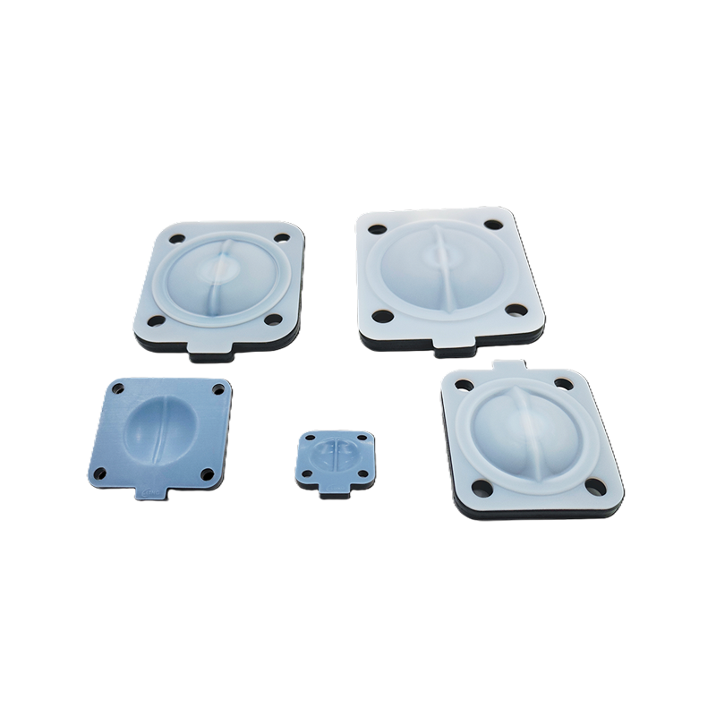
The diaphragm is both the functional heart of the valve and its primary consumable — its material must be chemically compatible with the process fluid, physically capable of the flexing required over the valve's cycle life, and suitable for the operating temperature range. Selecting an incompatible diaphragm material results in chemical attack that causes the diaphragm to swell, crack, delaminate, or perforate, either contaminating the process fluid with diaphragm material or allowing process fluid to bypass the diaphragm and contact the valve's mechanical internals. The following diaphragm materials cover the majority of industrial applications.
- EPDM (Ethylene Propylene Diene Monomer): The standard diaphragm material for water, steam, mild alkaline solutions, dilute acids, and most aqueous process fluids. EPDM has good resistance to ozone, UV, and heat (continuous service to approximately 120°C with steam), and is the material of choice for water treatment, pharmaceutical WFI (water for injection) systems, and general chemical service. It is not compatible with oils, hydrocarbons, or concentrated aromatic solvents.
- NR (Natural Rubber): Provides excellent flexibility and mechanical strength for high-cycle applications, with good resistance to dilute acids and alkalis. Natural rubber is used in pharmaceutical and food processing applications where the diaphragm must flex millions of times without fatigue failure. Not suitable for oils, petroleum products, or oxidizing media.
- PTFE (Polytetrafluoroethylene): PTFE-lined diaphragms consist of a PTFE membrane bonded to an elastomeric backing layer — the PTFE contact face provides near-universal chemical resistance across acids, alkalis, solvents, and oxidizing agents, while the elastomeric backing provides the flexibility needed for valve operation. PTFE diaphragms are specified for aggressive chemical service including concentrated acids, halogens, and most organic solvents. Their limitation is reduced flexibility compared to pure elastomer diaphragms, which reduces cycle life in high-frequency applications and requires greater actuator force to deflect the stiffer composite membrane.
- Viton (FKM/FPM): Fluoroelastomer diaphragms combining broad chemical resistance with better flexibility than PTFE composites. Excellent resistance to petroleum products, aromatic solvents, hydraulic fluids, and many aggressive chemicals. Suitable for service temperatures up to approximately 150°C. Used in oil and gas, petrochemical, and chemical manufacturing where hydrocarbon compatibility is required alongside diaphragm flexibility.
- Silicone: Food-grade and pharmaceutical-grade silicone diaphragms meet FDA, USP Class VI, and EU 10/2011 compliance requirements for food and drug contact applications. Silicone has outstanding biocompatibility and very low extractables, making it the material of choice for bioprocessing, beverage dispensing, and pharmaceutical fluid handling where regulatory compliance is mandatory. Its chemical resistance to non-polar solvents and concentrated acids is limited.
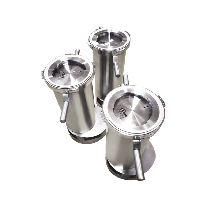
Body Materials and Their Application Context
The valve body must be chemically compatible with the process fluid and physically suitable for the operating pressure and temperature. The diaphragm design means the fluid contacts the body's wetted surfaces — the internal bore, the weir face, and the diaphragm underside — so body material selection is as important as diaphragm material selection for overall chemical compatibility.
- Cast iron: Used for water, non-corrosive fluids, and mild chemical service at lower cost. Not suitable for acidic or alkaline process fluids, and susceptible to corrosion in high-moisture environments if the external body is unpainted or unprotected.
- Stainless steel (316L): Standard for pharmaceutical, food processing, semiconductor, and chemical applications requiring corrosion resistance, hygienic design, and FDA/3A compliance. Electropolished internal surfaces minimize bacterial adhesion and facilitate clean-in-place (CIP) and steam-in-place (SIP) cleaning operations. Most expensive of the standard body materials but provides the combination of corrosion resistance and hygienic surface quality needed in regulated industries.
- PVC and CPVC: Thermoplastic body materials providing excellent resistance to strong acids, alkalis, and aqueous chemical solutions at moderate temperatures (PVC to 60°C, CPVC to 95°C). Widely used in chemical dosing systems, water treatment, and electroplating where metal contamination of the process fluid from a metal valve body would be unacceptable. Lightweight, low cost, and fully compatible with plastic piping systems without the need for transition couplings.
- PVDF (Polyvinylidene Fluoride): Superior chemical resistance to PVC/CPVC, including resistance to most organic solvents, halogens, and strong oxidizing acids. Used in ultra-pure water systems (semiconductor manufacturing), aggressive chemical handling, and high-purity pharmaceutical applications where both chemical resistance and very low extractables are required. More expensive than PVC but significantly extends service life in aggressive chemical environments.
Fail-Safe Actuation and Power Failure Behavior
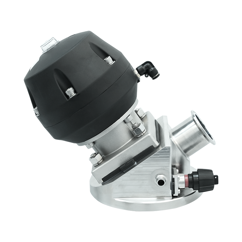
In any process application where the consequence of a valve staying in the wrong position during a power failure could result in process hazard, equipment damage, or product loss, the fail-safe behavior of the electric actuator must be specified as part of the valve selection process. Electric diaphragm valve actuators achieve fail-safe operation through two principal mechanisms.
Spring-return electric actuators use an internal spring that is compressed during normal electrically powered operation. On power loss, the spring drives the valve to its fail-safe position — either fully open or fully closed depending on the spring's pre-set orientation. This provides true fail-safe behavior without any stored electrical energy, battery, or capacitor requirement, but the spring force must be overcome by the electric motor during every opening or closing stroke, which requires more powerful motor selection and increases the actuator's overall size and cost for a given valve size. Battery backup electric actuators use an integrated rechargeable battery that maintains charge during normal operation and drives the motor to the fail-safe position on power loss detection. This allows the same actuator to be used in either fail-open or fail-closed mode without internal modification — the fail-safe direction is programmed rather than physically determined by spring orientation — but introduces battery maintenance requirements and the risk of fail-safe failure if the battery is discharged or degraded. Fail-in-place actuators — which simply hold their last position on power loss through motor self-locking or mechanical brake engagement — are specified where neither opening nor closing on power failure is appropriate and the valve should remain at its last commanded position until power and control signals are restored.
Modulating Control vs. On/Off Operation
Electric diaphragm valves are available in two fundamentally different control configurations that serve very different process control functions, and specifying the correct configuration for the application is essential for both process performance and valve longevity.
On/off electric diaphragm valves operate only in the fully open or fully closed position. The electric actuator drives the valve to one end-stop or the other in response to a binary control signal — typically a 24V DC or relay contact signal from a PLC or timer. On/off operation is appropriate for applications where the valve's function is simple flow isolation — dosing systems that require a defined volume to be dispensed before the valve closes, batch process filling systems, and on/off irrigation control. On/off valves cycle between their two end positions relatively infrequently in most process applications, which is consistent with the diaphragm's flexing being concentrated at the extremes of its travel where it is most predictable.
Modulating electric diaphragm valves position the diaphragm at intermediate positions in response to an analog control signal (most commonly 4 to 20 mA from a PLC or process controller) to regulate flow rate continuously. This capability is used in flow control loops, pressure regulation systems, and pH dosing applications where precise, continuously variable flow adjustment is required. Modulating operation subjects the diaphragm to flexing at positions across its full range of travel, which can produce a different fatigue pattern compared to on/off cycling — diaphragm life in modulating service depends on the amplitude and frequency of position changes and should be factored into maintenance scheduling. Modulating actuators also require more sophisticated position feedback systems — typically a 4 to 20 mA position transmitter or multi-turn encoder — to provide the closed-loop position control needed for precise flow regulation.
Installation, Commissioning, and Maintenance Considerations
Correct installation and systematic maintenance are as important to electric diaphragm valve reliability as correct specification. Even the most precisely specified valve will fail prematurely if installed incorrectly, commissioned without proper calibration, or maintained on a reactive rather than preventive basis.
- Orientation requirements: Most diaphragm valves can be installed in any orientation — horizontal pipe, vertical pipe, or at any angle — with certain limitations. Installations with the actuator pointing downward are generally avoided because diaphragm droop under gravity and potential ingress of leaked process fluid into the actuator housing become concerns. Where downward-actuator orientation is unavoidable, specify a valve with enhanced diaphragm support in the open position and confirm the actuator IP rating is adequate to handle any fluid that might migrate past the diaphragm during its service life.
- Actuator limit switch calibration: At commissioning, verify that the actuator's open and closed limit switches are correctly set to stop the motor at the precise fully-open and fully-closed positions. Limit switch settings that stop the motor before full closure result in seat leakage; settings that continue motor drive after the valve has reached its mechanical end-stop cause compressive overloading of the diaphragm and premature diaphragm failure through cold-flow deformation of the sealing surface. Follow the manufacturer's commissioning procedure for limit switch calibration rather than adjusting by feel or visual judgment.
- Diaphragm replacement intervals: Establish a preventive maintenance schedule for diaphragm replacement based on the manufacturer's recommended cycle life rating for the specific diaphragm material and service conditions, derated for the actual operating temperature, chemical concentration, and pressure differential. In high-cycle applications (more than 10,000 cycles per year) or aggressive chemical service, reduce replacement intervals from the standard recommendation. Maintaining a stock of replacement diaphragms on-site eliminates the lead time delay that extends unplanned downtime when a diaphragm fails during production.
- Inspect for diaphragm permeation in aggressive chemical service: In valves handling concentrated acids or solvents, diaphragm permeation — the slow diffusion of small molecules through the diaphragm material — can cause chemical attack of the compressor plate, spindle, and actuator internals over time even when the diaphragm appears visually intact. During scheduled maintenance, inspect the spindle and compressor plate for discoloration, corrosion pitting, or material loss that would indicate permeation attack, and replace diaphragms before permeation damage progresses to the actuator housing.
Electric diaphragm valves offer a combination of complete process fluid isolation, remote automated control, and broad chemical and hygienic service capability that makes them the correct solution for a wide range of demanding process applications — from pharmaceutical bioprocessing and semiconductor ultra-pure water systems to chemical dosing plants and industrial wastewater treatment. The investment in correctly specifying the diaphragm material, body material, actuator sizing, fail-safe configuration, and control interface for the specific application — rather than defaulting to standard catalog selections — consistently produces installations that achieve their design service life without the premature failures that misspecification inevitably generates.


