


Content
- 1 The Core Problem RTP Ports Solve in Aseptic Drug Manufacturing
- 2 How an RTP Valve Works: Alpha and Beta Port Mechanics
- 3 RTP Port Design Variants and Their Applications
- 4 Regulatory and Validation Requirements for RTP Systems
- 5 Key Performance Parameters to Evaluate When Selecting an RTP System
- 6 Integration of RTP Ports into Isolator and RABS Design
- 7 Maintenance, Seal Replacement, and Ongoing Performance Monitoring
In pharmaceutical manufacturing, the aseptic production of sterile drug products demands an unwavering commitment to contamination control at every stage of the process. One of the most technically demanding moments in any aseptic workflow is the transfer of materials — components, containers, equipment, or in-process product — between areas of different cleanliness classification. Every time an isolator, restricted access barrier system (RABS), or cleanroom is opened to introduce or remove material, a potential pathway for microbial, particulate, and cross-contamination is created. The Rapid Transfer System Port, universally referred to as the RTP port or RTP valve, exists specifically to eliminate that risk by enabling fully contained, sterility-assured material transfer without any break in the controlled environment. Understanding how RTP ports work, how they are validated, and how to select the right system for a specific pharmaceutical application is fundamental knowledge for anyone involved in aseptic process design, facility qualification, or contamination control.
The Core Problem RTP Ports Solve in Aseptic Drug Manufacturing
Aseptic drug manufacturing requires that sterile product never contacts a non-sterile surface or environment from the point of sterilization through to final container closure. This requirement creates a fundamental engineering challenge: how do you move physical objects — vials, stoppers, lyophilized product, tooling, or samples — into and out of an isolator or cleanroom without creating even a momentary uncontrolled opening between the sterile interior and the surrounding environment?
Traditional approaches — such as transfer airlocks with sequential door interlocks, spray-and-wipe decontamination procedures, or laminar flow hoods — all require human intervention at the interface, introduce procedural variability, and rely on operator technique for their effectiveness. These approaches can be adequate for lower-risk transfers in Grade C or D environments, but they are fundamentally insufficient for direct transfer into Grade A isolators handling high-value, high-risk sterile products such as injectable biologics, cytotoxic drugs, advanced therapy medicinal products (ATMPs), or radiopharmaceuticals.
The RTP port solves this problem through a mechanical design that physically prevents any surface that has been exposed to the external environment from entering the sterile zone, and simultaneously prevents the sterile interior from being exposed to the exterior — regardless of operator technique. The principle is elegant: two half-doors, one fixed on the isolator wall (the alpha port) and one attached to the transfer container (the beta port), can only be joined together and opened inward as a locked pair. The exterior-facing surfaces of both doors are joined together and remain permanently on the outside; only the previously interior-facing surfaces are ever exposed to the sterile zone.
How an RTP Valve Works: Alpha and Beta Port Mechanics
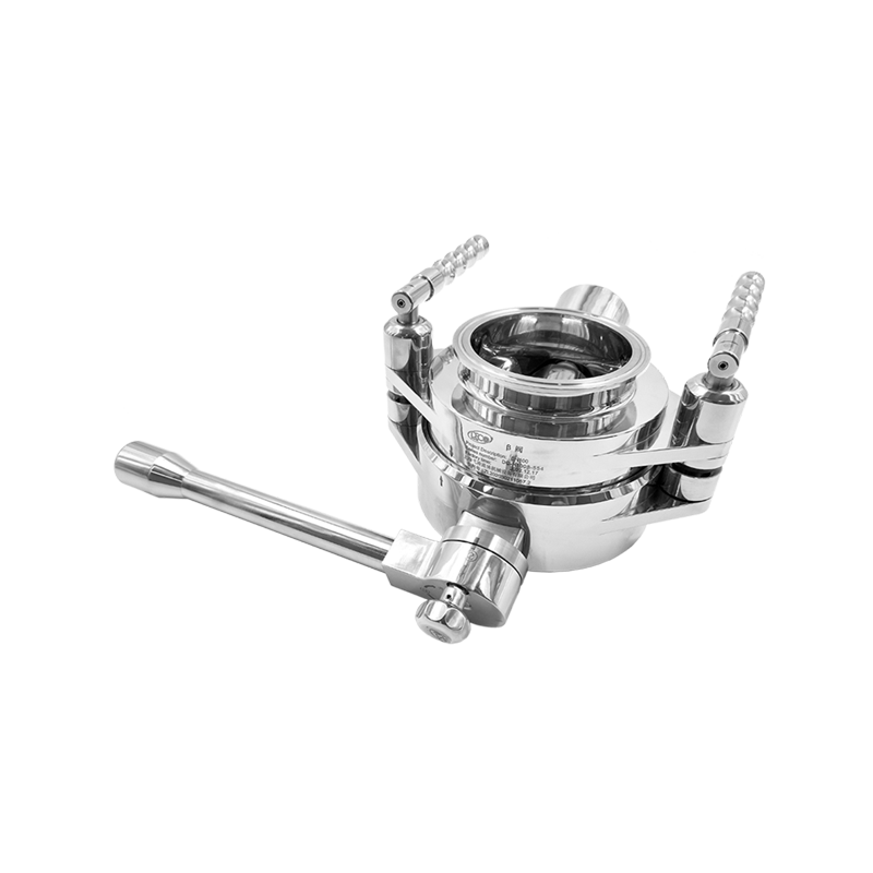
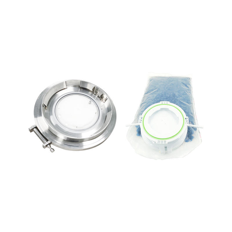
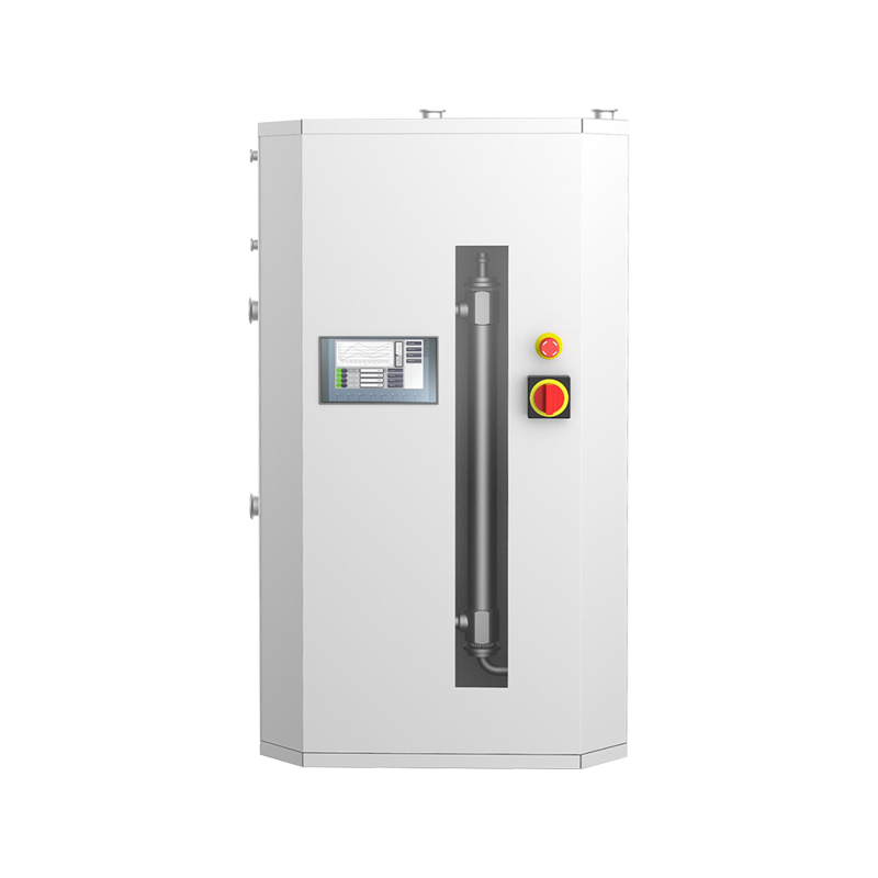
The RTP system consists of two complementary components that must always function together. The alpha port is the fixed component permanently installed in the wall of an isolator, RABS enclosure, or cleanroom access panel. It contains a circular door with a locking mechanism and, in most designs, a decontamination capability. The beta port is the removable component — typically a rigid transfer container, bag, or drum fitted with a matching door — that is brought to the alpha port for connection.
The connection sequence begins when the beta port flange is offered up to the alpha port and rotated to engage the locking mechanism — typically a multi-point bayonet lock requiring a defined angular rotation to fully engage. Once locked, the two doors are mechanically coupled together as a single unit. The locking mechanism simultaneously releases the combined door assembly, which is then swung or slid inward into the isolator. Critically, the outer surface of the alpha door (which was previously exposed to the isolator exterior) is now bonded face-to-face with the outer surface of the beta door (which was previously exposed to the external transfer environment). These two contaminated surfaces are permanently joined together throughout the transfer process and are never exposed to the sterile interior.
When the transfer is complete, the combined door is returned to its closed position, the beta container is rotated to disengage the bayonet lock, and the beta port is removed. The alpha port door returns to its sealed position, maintaining the integrity of the isolator. The entire transfer sequence has been completed without any uncontrolled pathway between the isolator interior and the external environment at any point in the process.
RTP Port Design Variants and Their Applications
While the alpha-beta principle is consistent across all RTP systems, significant design variations exist that affect suitability for different pharmaceutical applications. Understanding these variants allows process engineers to select the system best matched to their specific transfer requirements.
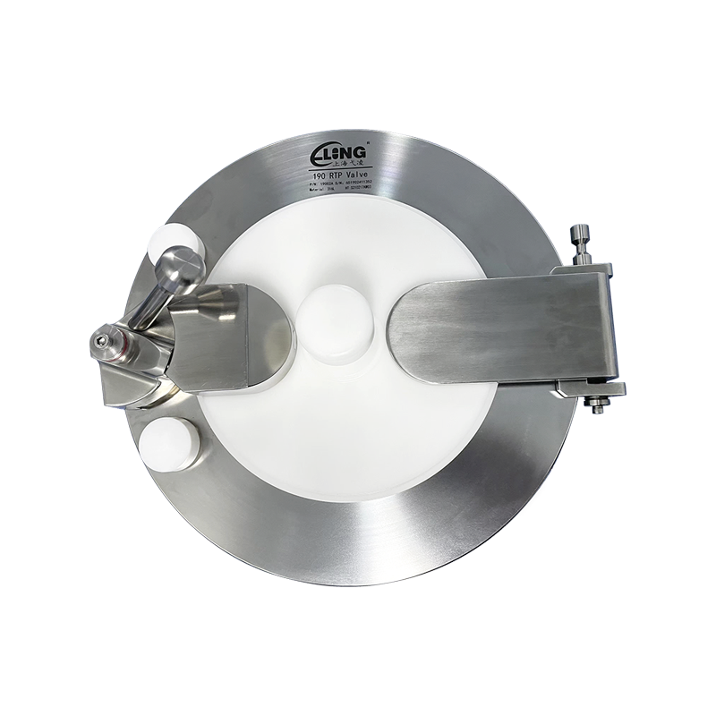
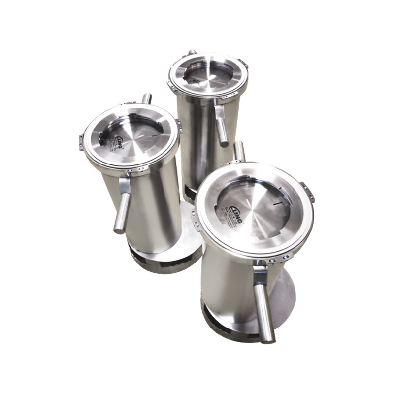
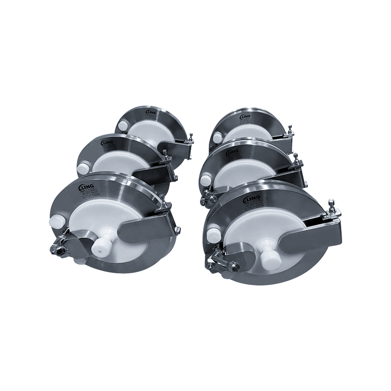
Standard Circular RTP Ports
The most widely used RTP format uses a circular door with a diameter typically ranging from 105 mm to 460 mm, with 190 mm and 320 mm being the most common sizes in pharmaceutical isolator installations. The circular geometry provides a uniform sealing surface and a mechanically efficient bayonet locking mechanism. Standard circular ports are used for transferring components such as stoppered vials, filled syringes, stoppers, and small equipment items. They are compatible with rigid transfer containers, flexible bags supported by rigid outer frames, and drum adapters for bulk component transfer.
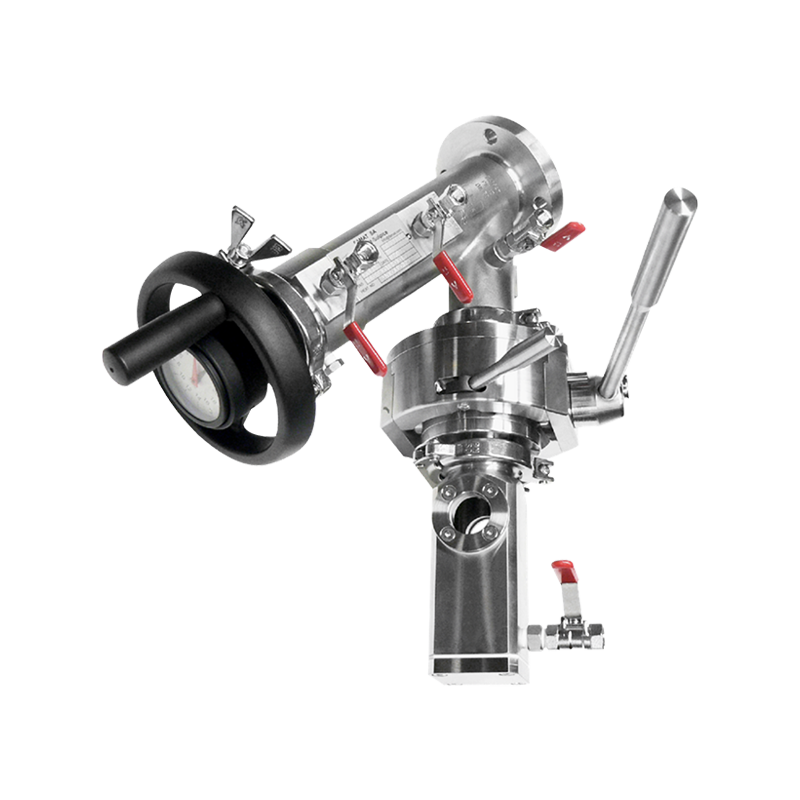
Decontaminating RTP Ports
For transfers requiring an additional bio-decontamination step — particularly when items entering the isolator cannot be pre-sterilized externally — decontaminating RTP ports incorporate a small annular decontamination chamber between the alpha and beta doors. After the beta container is locked to the alpha port but before the combined doors are opened, a sporicidal agent (typically vaporized hydrogen peroxide, VHP) is injected into this annular space, decontaminating the surfaces of both doors and the inner surface of the beta container flange. This approach provides a validated log reduction in bioburden at the transfer interface and is required for transfers into isolators used for sterility testing or highly sensitive biological processes.
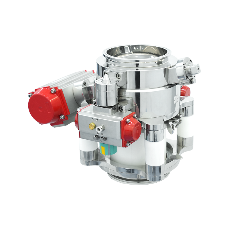
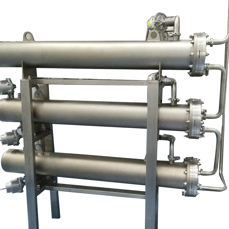
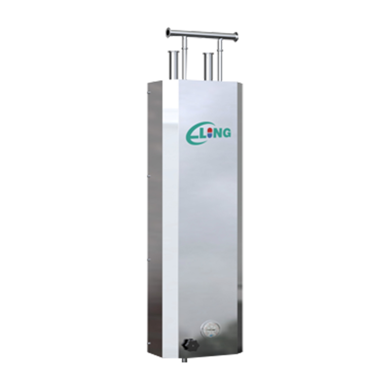
Continuous Liner and Drum Transfer Systems
For high-volume bulk transfers — bulk lyophilized product, large quantities of components, or waste removal — continuous liner systems and drum transfer ports extend the RTP principle to larger formats. Continuous liner systems use a sleeve of flexible plastic film pre-welded between the alpha port and the transfer container; material passes through the sleeve, which is then heat-sealed and cut to close off each transfer without ever exposing the isolator interior. Drum transfer ports use an oversized alpha-beta configuration accommodating standard pharmaceutical drums of 10–200 liter capacity, enabling the transfer of large bulk quantities into containment isolators for highly potent compound handling.
Regulatory and Validation Requirements for RTP Systems
The use of RTP ports in aseptic drug manufacturing is not simply a best practice — it is increasingly a regulatory expectation for isolator-based aseptic processes reviewed under the EU GMP Annex 1 (2022 revision), FDA's Guidance for Industry on Sterile Drug Products Produced by Aseptic Processing, and PIC/S PE 009. The 2022 revision of EU GMP Annex 1, in particular, establishes a detailed framework for contamination control strategy (CCS) that explicitly addresses the transfer of materials into and out of aseptic manufacturing environments, placing a high expectation on the use of validated closed transfer systems.
Validation of an RTP system for aseptic pharmaceutical use requires demonstrating three primary performance attributes: physical containment integrity, microbial ingress prevention, and decontamination efficacy (where applicable). Physical containment is typically demonstrated through pressure hold testing of the assembled alpha-beta interface, confirming that no leak path exists at the sealing surfaces under the differential pressure conditions maintained in the isolator. Microbial ingress prevention is validated through challenge studies in which the transfer sequence is performed with high-concentration microbial contamination applied to the external surfaces of the transfer container, and the isolator interior is subsequently tested to confirm zero contamination ingress.
For decontaminating RTP ports incorporating VHP treatment, sporicidal efficacy validation follows the ISO 14937 framework, typically requiring demonstration of a minimum 6-log reduction of Geobacillus stearothermophilus biological indicators placed at the most challenging locations within the decontamination chamber. Cycle development must account for the specific geometry of the port and the aeration characteristics of the VHP generator being used, as residual VHP levels must be reduced to below 1 ppm before the combined door is opened into the isolator to protect product and operators.
Key Performance Parameters to Evaluate When Selecting an RTP System
| Parameter | Typical Specification | Why It Matters |
| Port diameter | 105 mm – 460 mm | Must accommodate largest item being transferred |
| Sealing mechanism | EPDM or silicone O-ring, multi-point bayonet | Maintains leak-tight seal under isolator pressure differential |
| Material of construction | 316L stainless steel, PEEK, or HDPE | Must be compatible with VHP, IPA, and cleaning agents |
| Decontamination capability | Integrated VHP annular chamber (optional) | Required for sterility test isolators and high-risk transfers |
| Pressure differential rating | ±200 Pa to ±500 Pa (depending on isolator design) | Seal must maintain integrity at operational positive or negative pressure |
| Cycle life | 10,000 – 50,000+ connection cycles | Determines maintenance and seal replacement intervals |
| Regulatory documentation | FAT/SAT protocols, IQ/OQ/PQ support package | Required for GMP qualification and regulatory submission support |
Integration of RTP Ports into Isolator and RABS Design
RTP ports must be specified and positioned during the early design phase of an isolator or RABS enclosure — retrofitting ports into an existing enclosure wall is technically possible but significantly more complex than integrating them at the design stage. The number, size, and location of RTP ports should be determined through a detailed material flow analysis for the process, mapping every material that will enter or leave the isolator during a production campaign, including raw materials, components, in-process samples, waste, and maintenance items.
Port location on the isolator wall must balance ergonomic accessibility for operators (ports should be reachable without awkward postures that increase the risk of handling errors), cleanability (ports should be positioned to avoid dead zones that accumulate product or cleaning agent residue), and airflow characteristics (large ports should not be positioned where their open door could disrupt the unidirectional airflow pattern protecting the Grade A zone). For isolators with more than three or four RTP ports, a 3D ergonomic and airflow simulation is a worthwhile investment during the design phase to identify potential issues before fabrication.
Maintenance, Seal Replacement, and Ongoing Performance Monitoring
The sealing O-rings and gaskets in RTP ports are the consumable components that most directly affect containment performance over the operational life of the system. EPDM and silicone O-rings used in pharmaceutical RTP ports are subject to compression set — a permanent reduction in the cross-sectional diameter of the O-ring caused by sustained compression — which reduces the sealing force and eventually allows leak paths to develop. The rate of compression set depends on the O-ring material, the temperature and chemical environment, and the number of connection and disconnection cycles the port undergoes.
Manufacturers typically specify O-ring replacement intervals based on cycle count rather than calendar time, with intervals ranging from 500 to 5,000 cycles depending on the specific O-ring material and port design. Facilities should implement a cycle-counting system — either manual logs or automated counters — to track when each port reaches its replacement threshold. Between planned O-ring replacements, leak testing of each port at regular intervals (typically every six months or following any maintenance event) using a pressure hold or tracer gas test provides ongoing assurance that seal integrity is maintained. Any port that fails a leak test should be taken out of service, the O-ring replaced, and the port re-qualified before returning to aseptic service.


