


Content
- 1 How a Pharmaceutical Electric Diaphragm Valve Works
- 2 Why Diaphragm Valves Are Preferred in Pharmaceutical Systems
- 3 Materials of Construction for Pharmaceutical Service
- 4 Electric Actuator Types and Control Options
- 5 Hygienic Standards and Regulatory Compliance Requirements
- 6 Validation and Documentation Requirements
- 7 Key Selection Criteria for Pharmaceutical Electric Diaphragm Valves
- 8 Maintenance Best Practices for Long-Term Reliability
The pharmaceutical electric diaphragm valve occupies a uniquely critical position in biopharmaceutical manufacturing, sterile water systems, and drug production facilities. It combines the hygienic flow control characteristics of the diaphragm valve — a design inherently suited to sanitary service due to its complete separation of the fluid path from the valve actuating mechanism — with the precision, repeatability, and automation capability of electric actuation. In pharmaceutical environments governed by cGMP (current Good Manufacturing Practice) regulations, FDA guidelines, and international standards such as ASME BPE and ISO 14159, every component in a fluid handling system must be demonstrably cleanable, free of dead legs that harbor biofilm, and capable of being validated for its intended service. The electric diaphragm valve, when correctly specified and maintained, satisfies all of these requirements while providing the remote control and position feedback capabilities that modern automated pharmaceutical production demands.
How a Pharmaceutical Electric Diaphragm Valve Works
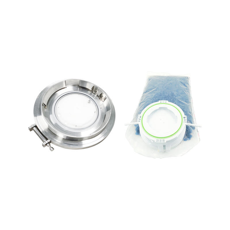
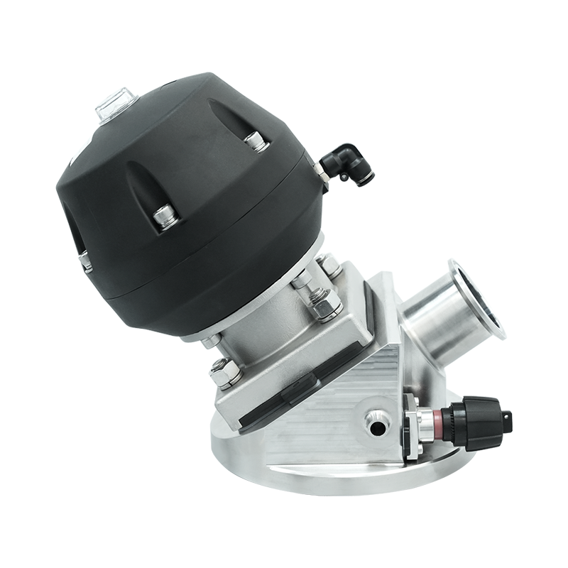
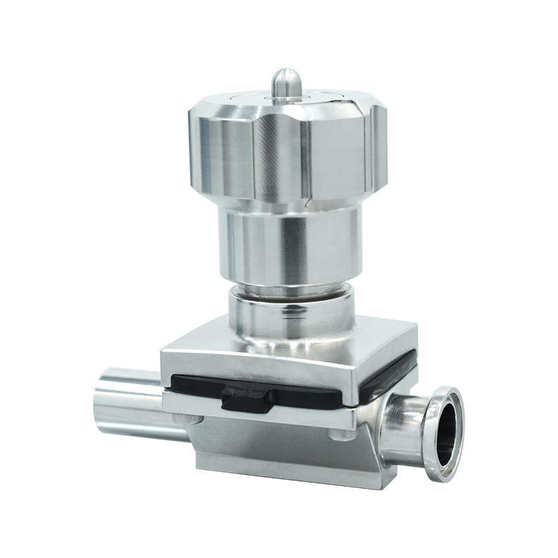
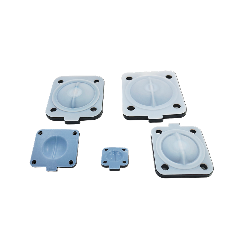
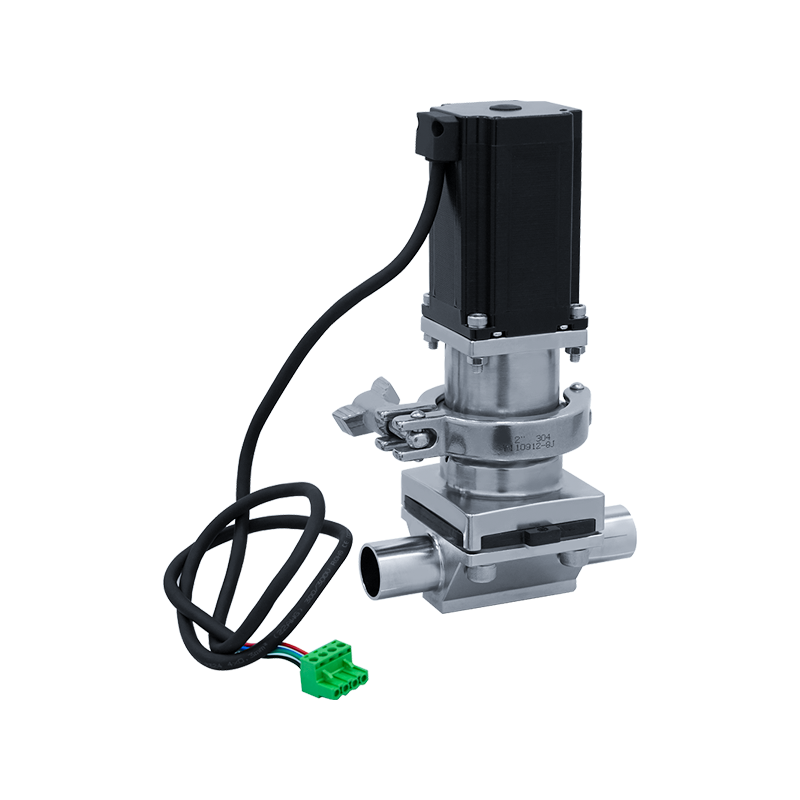
The operating principle of a diaphragm valve is mechanically straightforward but functionally elegant in the context of hygienic service. A flexible diaphragm — typically molded from PTFE, EPDM, or a composite of both — is clamped between the valve body and a bonnet assembly. The diaphragm forms a complete barrier between the fluid in the flow path and the actuating mechanism above it. When the electric actuator drives the compressor downward onto the diaphragm through a central stem, the diaphragm deflects into the valve body and presses against a weir or saddle feature machined into the body — closing the valve and stopping flow. When the actuator retracts the compressor, the diaphragm's inherent elasticity or a return spring causes it to lift away from the weir, opening the flow path.
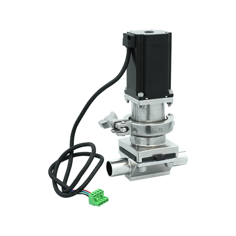
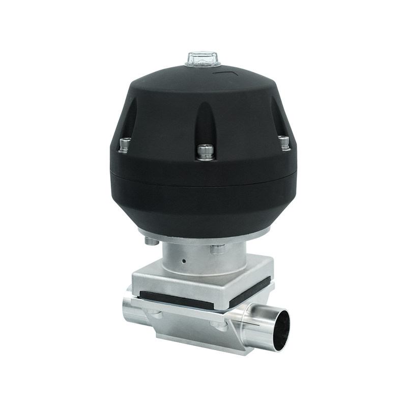
The electric actuator replaces the manual handwheel or pneumatic cylinder used in non-automated versions with a servomotor or stepper motor assembly driving a precision linear or rotary-to-linear mechanism. This electric drive provides several functional advantages over pneumatic actuation in pharmaceutical applications: it does not require a compressed air supply at each valve location — eliminating the contamination risk of oil-laden instrument air in sterile environments — it can be precisely positioned at any point in its stroke range for modulating service, and it provides inherent position feedback through encoder or potentiometer signals that can be integrated directly into a plant DCS or SCADA system without additional positioner hardware.
Why Diaphragm Valves Are Preferred in Pharmaceutical Systems
The dominance of diaphragm valves in pharmaceutical fluid handling is not accidental — it reflects a combination of design features that align precisely with the hygiene, cleanability, and regulatory requirements of drug manufacturing environments in ways that alternative valve types cannot match.
- No dead legs in the flow path: The weir-body geometry of a pharmaceutical diaphragm valve, combined with correct installation in a self-draining configuration, eliminates the stagnant fluid pockets that harbor microbial contamination in ball valves, gate valves, and globe valves with complex internal geometries. ASME BPE specifies maximum dead leg ratios for pharmaceutical piping systems, and properly installed diaphragm valves readily comply with these requirements.
- Complete separation of fluid and mechanism: The diaphragm provides an absolute barrier between the process fluid and the valve bonnet, stem, and actuator. There is no possibility of lubricants, metallic wear particles, or atmospheric contaminants from the actuating mechanism entering the fluid path — a characteristic that is particularly valuable in sterile water for injection (WFI), purified water, and direct product contact applications where any contamination of the fluid is a serious regulatory and product quality concern.
- CIP and SIP compatibility: Pharmaceutical diaphragm valves are fully compatible with Clean-in-Place (CIP) and Steam-in-Place (SIP) processes that are the standard cleaning and sterilization methodology in modern pharmaceutical manufacturing. The smooth, crevice-free fluid contact surfaces are effectively reached and sterilized by CIP chemicals and steam without disassembly, enabling validated cleaning cycles that meet regulatory requirements without interrupting production for manual valve servicing.
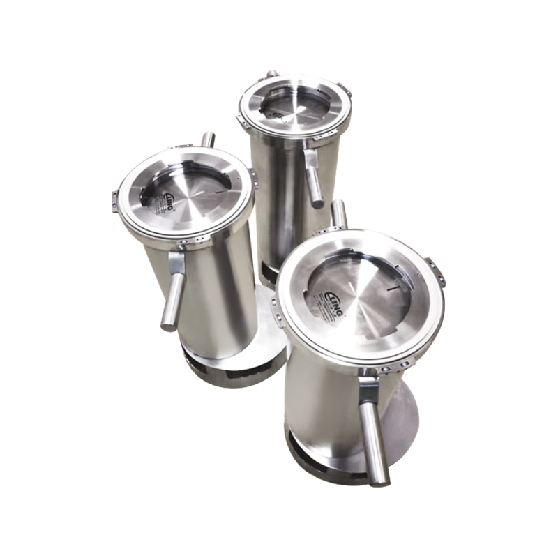
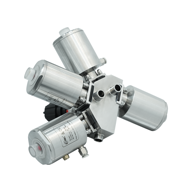
- Visual and physical drainability: Pharmaceutical diaphragm valve bodies are available in T-body, angled body, and straight-through configurations, with body geometries designed to drain completely under gravity when installed at the specified angle. Complete drainability is a regulatory requirement in many pharmaceutical water and product systems because retained liquid between process runs creates conditions for microbial proliferation.
Materials of Construction for Pharmaceutical Service
Material selection for pharmaceutical electric diaphragm valves is governed by the requirements for chemical compatibility with process fluids and cleaning agents, compliance with regulatory material standards, surface finish specifications that inhibit microbial adhesion, and traceability documentation that supports regulatory submissions and validation activities.
| Component | Standard Material | Key Properties | Regulatory Reference |
| Valve Body | 316L Stainless Steel | Corrosion resistance, weldability, low carbon | ASME BPE, EN 10272 |
| Diaphragm | PTFE / EPDM composite | Chemical inertness, steam resistance, FDA compliance | FDA 21 CFR, USP Class VI |
| Bonnet | 316L SS or PP | Non-product contact, corrosion resistant | ASME BPE |
| Body Seals / O-rings | EPDM, PTFE encapsulated | Elasticity, steam compatibility, extractables | USP Class VI, FDA 21 CFR |
| Internal Surface Finish | Ra ≤ 0.5 μm (electropolished) | Reduced biofilm adhesion, enhanced cleanability | ASME BPE SF1–SF4 |
316L stainless steel — the low-carbon variant of 316 austenitic stainless steel — is universally specified for pharmaceutical valve bodies because its low carbon content minimizes carbide precipitation at heat-affected zones during welding, preserving corrosion resistance in welded assemblies that would otherwise be compromised. The molybdenum content of 316L provides superior resistance to chloride pitting compared to 304 stainless steel, important given that pharmaceutical cleaning agents frequently contain chlorinated compounds. Surface finish is specified in terms of Ra (arithmetic mean roughness) — typically Ra ≤ 0.8 μm for standard pharmaceutical service and Ra ≤ 0.5 μm or better for WFI and injectable product systems — with electropolishing applied as an additional processing step that removes surface irregularities, depletes iron-rich surface layers, and produces a chromium-oxide-enriched passive film that enhances corrosion resistance and reduces protein adhesion.
Electric Actuator Types and Control Options
The electric actuator fitted to a pharmaceutical diaphragm valve determines the valve's control capabilities, its compatibility with plant automation infrastructure, its power requirements, and its behavior under power failure conditions — all of which must be specified with attention to the requirements of each specific application within the process system.
On/Off Electric Actuators
On/off electric actuators drive the valve between its fully open and fully closed positions on receipt of a digital control signal, with typical stroke times of 5–30 seconds depending on actuator size and valve DN. They are used in isolation, diversion, and sequencing applications where the valve is only ever required to be in one of two discrete states. Most pharmaceutical-grade on/off electric actuators incorporate end-of-travel limit switches that provide open and closed position confirmation signals to the control system — a functional requirement for validated pharmaceutical processes where positive confirmation of valve state is needed to satisfy batch record documentation requirements and prevent process deviations caused by incomplete valve operation.
Modulating Electric Actuators
Modulating electric actuators accept an analog control signal — typically 4–20 mA or 0–10 V DC — and position the valve at a continuously variable point in its stroke range proportional to the signal value. This capability enables flow control and pressure regulation applications where the valve must maintain a specific flow rate or upstream/downstream pressure setpoint as process conditions change. Pharmaceutical applications for modulating electric diaphragm valves include purified water flow balancing in distribution loops, buffer preparation vessel fill control, bioprocess media addition to bioreactors, and CIP flow rate regulation during cleaning cycles. Modulating actuators incorporate position feedback transmitters — either analog output 4–20 mA or digital fieldbus signals — that allow the DCS to verify actual valve position against the commanded setpoint and implement closed-loop control with position-based feedback.
Fail-Safe Behavior Specification
The behavior of a pharmaceutical electric diaphragm valve under power failure conditions is a critical safety and process integrity specification that must be deliberately defined for each valve position. Fail-closed (FC) actuators incorporate a spring return mechanism that drives the valve to the closed position when power is lost — appropriate for isolation valves on hazardous or product-critical lines where uncontrolled flow in the event of a power interruption is unacceptable. Fail-open (FO) actuators spring-return to the open position on power loss — used on cooling water supplies to bioreactors and other heat-generating equipment where loss of cooling flow during a power failure would cause greater damage than uncontrolled flow. Fail-in-last-position (FL) actuators use an electronic latch or mechanical lock to hold the valve at its last commanded position during a power failure — applicable to applications where neither open nor closed is inherently safer and where sudden valve movement during a power event would itself cause a process disturbance.
Hygienic Standards and Regulatory Compliance Requirements
Pharmaceutical electric diaphragm valves used in drug manufacturing must comply with a layered set of international standards and regulatory requirements that together define the minimum acceptable design, material, and documentation standards for equipment in contact with pharmaceutical products or process utilities.
- ASME BPE (Bioprocessing Equipment): The ASME Bioprocessing Equipment standard is the primary technical reference for pharmaceutical fluid handling component design in North American and many international markets. It specifies dimensional standards for tubing and fittings, surface finish classifications, material requirements, weld quality criteria, and cleanability design guidelines that pharmaceutical diaphragm valves must meet to be specified in cGMP-compliant systems.
- FDA 21 CFR Part 211: The FDA's current Good Manufacturing Practice regulations for finished pharmaceuticals require that equipment surfaces contacting drug products or drug product containers be constructed of materials that are non-reactive, non-additive, and non-absorptive — requirements that stainless steel bodies and PTFE-faced diaphragms satisfy for the vast majority of pharmaceutical service conditions.
- USP Class VI Elastomers: Diaphragms and O-rings in pharmaceutical valves should be certified to USP Class VI biological reactivity testing, which evaluates the cytotoxicity, systemic toxicity, and intracutaneous reactivity of elastomeric materials that may contact pharmaceutical products. Class VI certification is a minimum requirement for product contact elastomers and is increasingly required for all wetted elastomers in pharmaceutical utility systems as well.
- EHEDG (European Hygienic Engineering and Design Group): For European pharmaceutical facilities, EHEDG certification of diaphragm valve designs provides documented evidence of hygienic design compliance, including cleanability testing that demonstrates the valve meets quantitative microbial reduction criteria under standardized CIP conditions. EHEDG-certified valves simplify the validation documentation process for European regulatory submissions.
- 3-A Sanitary Standards: The 3-A Sanitary Standards program, primarily used in the food, beverage, and dairy industries but increasingly referenced in pharmaceutical applications, certifies equipment designs against sanitary design criteria and provides third-party verification that claimed compliance is legitimate — reducing the burden on pharmaceutical manufacturers to independently verify supplier design claims during equipment qualification activities.
Validation and Documentation Requirements
In pharmaceutical manufacturing, equipment cannot simply be purchased and installed — it must be qualified through a structured validation process that documents evidence of suitability for its intended use. Pharmaceutical electric diaphragm valves must be supported by a documentation package from the manufacturer that enables and supports the installation qualification (IQ), operational qualification (OQ), and performance qualification (PQ) activities required by cGMP regulations.
The minimum documentation package for a pharmaceutical-grade electric diaphragm valve typically includes material certificates (EN 10204 3.1 material test reports for stainless steel components), surface finish measurement records documenting Ra values at specified measurement locations, pressure test certificates, dimensional inspection reports, FDA-compliant elastomer certificates with USP Class VI test reports, and CE or other applicable conformity declarations for the electric actuator. Valve manufacturers with established pharmaceutical market presence typically offer enhanced documentation packages that include factory acceptance test (FAT) protocols, cleaning and sterilization validation support documentation, and change control commitments that notify customers of any changes to materials or manufacturing processes that could affect qualification status — the last of these being particularly important for pharmaceutical customers whose validation activities are invalidated by undocumented changes to previously qualified equipment.
Key Selection Criteria for Pharmaceutical Electric Diaphragm Valves
Selecting the appropriate pharmaceutical electric diaphragm valve for a specific application requires working through a structured set of technical, regulatory, and operational criteria. Overlooking any of these factors during the specification process can result in a valve that fails to meet regulatory requirements, performs inadequately in service, or requires premature replacement.
- Process fluid and cleaning agent compatibility: Verify compatibility of all wetted materials — body alloy, diaphragm compound, and O-ring material — with the specific process fluid, its concentration and temperature, and all CIP and SIP agents used in the cleaning and sterilization protocol. Aggressive cleaning agents including peracetic acid, sodium hydroxide, and nitric acid impose different compatibility requirements on elastomers than the process fluids themselves, and compatibility must be verified for the entire service chemical envelope, not just the process fluid in isolation.
- Pressure and temperature ratings: Confirm that the valve's maximum allowable working pressure (MAWP) and temperature ratings cover the most demanding conditions the valve will experience in service, including CIP temperatures that commonly reach 85–90°C and SIP conditions at 121–134°C with steam pressure. Note that diaphragm life is significantly reduced at elevated temperatures, and diaphragm replacement intervals should be planned accordingly for valves regularly exposed to SIP cycles.
- Control system interface requirements: Define the required control signal type (digital on/off, analog 4–20 mA, fieldbus protocol such as PROFIBUS, FOUNDATION Fieldbus, or HART), power supply voltage, and feedback signal requirements before specifying the actuator. Ensure the selected actuator is compatible with the plant's DCS or PLC infrastructure without requiring additional signal conversion hardware that adds complexity and potential failure points to the control loop.
- Body configuration and installation orientation: Select the valve body geometry — weir body, T-body, or angle body — appropriate for the piping layout, ensuring the installed valve drains completely and does not create dead legs exceeding the system design specification. Confirm the valve can be installed in the required orientation — most pharmaceutical diaphragm valves must be installed with the bonnet above horizontal to ensure gravity-assisted draining — and that the installed position provides adequate access for diaphragm replacement without requiring pipe disassembly.
- Diaphragm replacement accessibility and frequency: Diaphragm replacement is the primary maintenance activity for pharmaceutical diaphragm valves, and its frequency depends on operating pressure, temperature, cycling frequency, and chemical exposure. Evaluate how accessible the valve bonnet is in the installed position and whether the bonnet design allows diaphragm replacement without special tools or extended downtime. Some manufacturers offer quick-release bonnet designs specifically intended to minimize diaphragm replacement time in high-frequency cycling applications.
- Manufacturer validation support capability: Assess the valve manufacturer's experience in pharmaceutical markets and their ability to provide the qualification documentation, change control commitments, and technical support for validation activities that pharmaceutical customers require. A technically superior valve from a manufacturer without pharmaceutical market experience and documentation infrastructure can create significantly more validation effort and regulatory risk than a well-documented product from an established pharmaceutical valve supplier.
Maintenance Best Practices for Long-Term Reliability
Maintaining pharmaceutical electric diaphragm valves correctly over their service life protects both the regulatory compliance status of the facility and the product quality assurance system that depends on these valves performing reliably and predictably throughout every production and cleaning cycle.
Diaphragm inspection and replacement on a risk-based preventive maintenance schedule — rather than waiting for visible diaphragm failure that could contaminate process fluid with elastomer fragments — is the cornerstone of pharmaceutical diaphragm valve maintenance. Establish replacement intervals based on manufacturer recommendations, actual service conditions, and the consequences of an in-service diaphragm failure in each valve position. Critical valves on sterile product lines or WFI systems warrant more conservative replacement intervals than low-criticality utility valves. Keep detailed maintenance records for each valve including installation date, diaphragm replacement history, and any anomalies observed during maintenance — this documentation supports both the plant's maintenance management system and the regulatory inspection readiness of the facility. For the electric actuator, verify position feedback calibration annually and after any maintenance that involves actuator removal, as calibration drift can cause the valve to report a false position state to the control system, creating potential for undetected process deviations in automated production sequences.


