


Content
- 1 How an Electric Diaphragm Valve Works and Why It Differs from Other Valve Types
- 2 Key Components and Their Functions
- 3 Industrial Applications Across Key Sectors
- 4 Electric vs. Pneumatic Diaphragm Valves: A Direct Comparison
- 5 Selection Criteria: Matching the Valve to the Application
- 6 Maintenance Practices That Extend Service Life
How an Electric Diaphragm Valve Works and Why It Differs from Other Valve Types
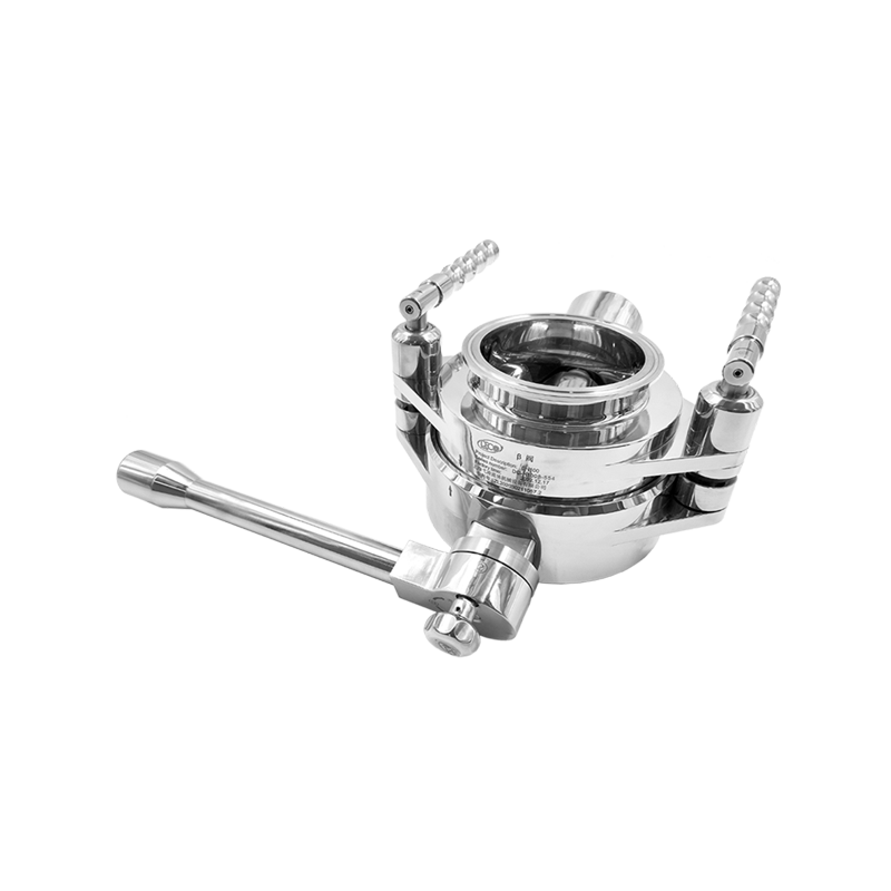
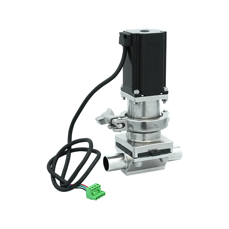
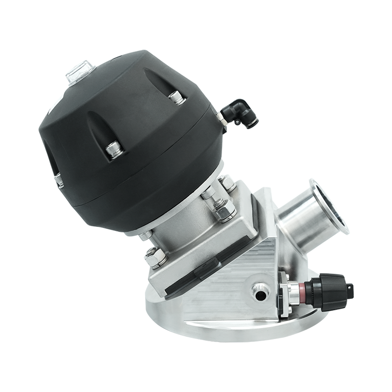
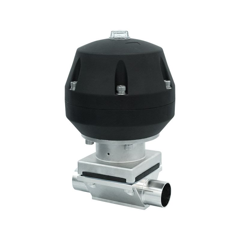
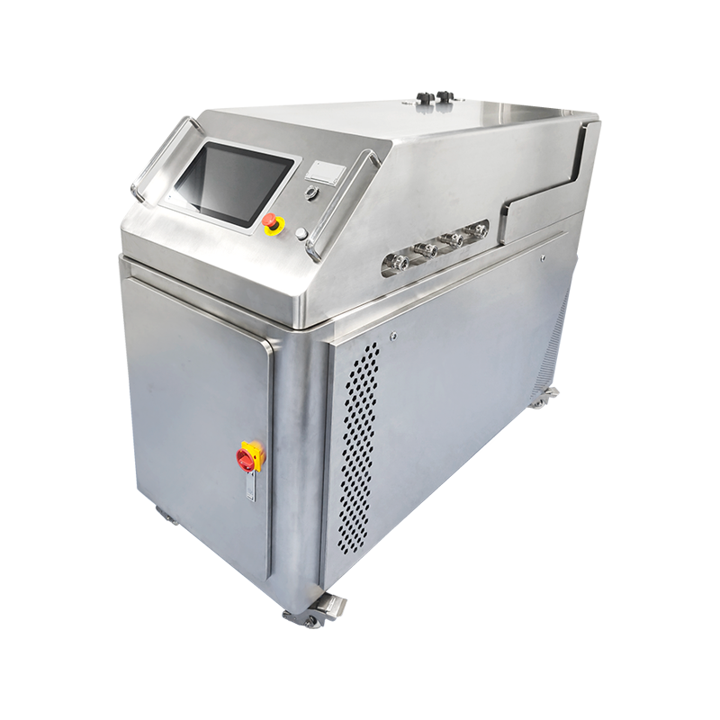
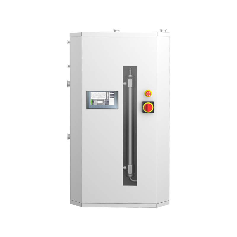
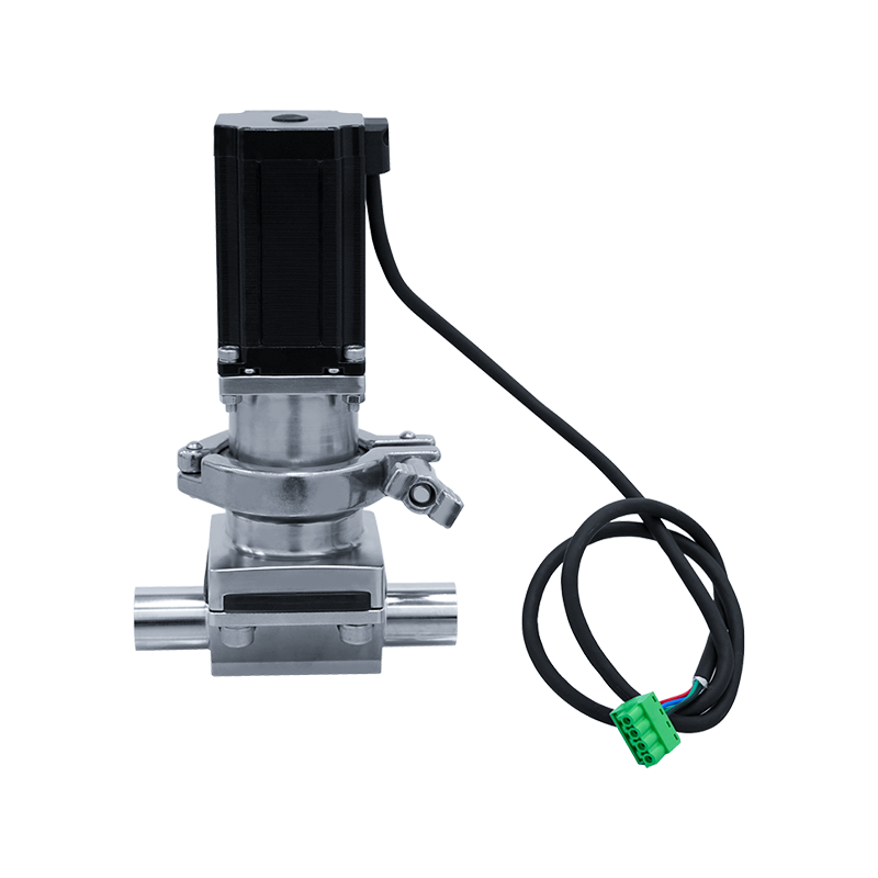
An electric diaphragm valve combines two distinct mechanical systems into a single unit: a diaphragm-based flow control body and an electric actuator that drives it. The valve body contains a flexible diaphragm — typically made from rubber, EPDM, PTFE, or other elastomers — that is pressed against a weir or seat to block flow, or lifted away from it to allow fluid to pass. The electric actuator sits above the valve body and converts electrical energy into linear or rotary mechanical force that moves the diaphragm up and down in response to control signals. This arrangement eliminates the need for a compressed air supply, which is the key operational difference between electric and pneumatic diaphragm valves.
Because the diaphragm is the only component in direct contact with the process fluid, the actuator mechanism and all internal moving parts remain completely isolated from what flows through the valve. This physical separation is the defining engineering advantage of the diaphragm valve design. Aggressive chemicals, slurries with suspended solids, viscous fluids, and sterile process streams can all be handled without contaminating or corroding the actuator components. The electric actuator receives its signal from a control system — typically a 4–20 mA analog signal, a digital on/off command, or a fieldbus protocol — and positions the diaphragm accordingly, enabling precise remote control without manual intervention.
Key Components and Their Functions
Understanding the function of each component in an electric diaphragm valve helps engineers select the right configuration for a specific application and diagnose issues when performance falls outside acceptable parameters.
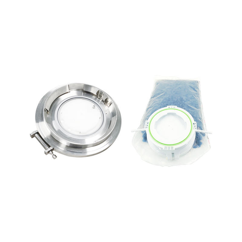
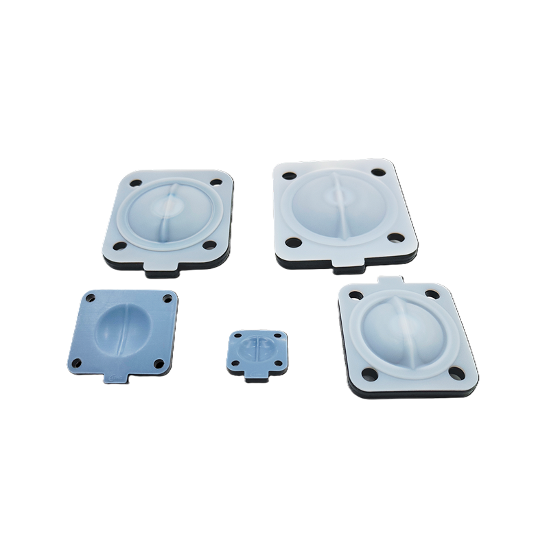
- Diaphragm: The diaphragm is the sealing element and the only wetted moving part. Its material must be chemically compatible with the process fluid and able to withstand the operating temperature and pressure range. EPDM is widely used for water and mild chemical service; PTFE is preferred for strong acids, solvents, and high-purity pharmaceutical applications; neoprene suits general-purpose industrial use. Diaphragm life varies by cycle frequency, pressure differential, and fluid characteristics, making it the primary consumable component requiring periodic replacement.
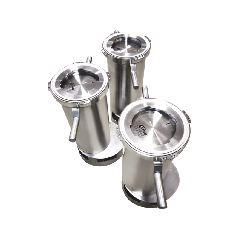
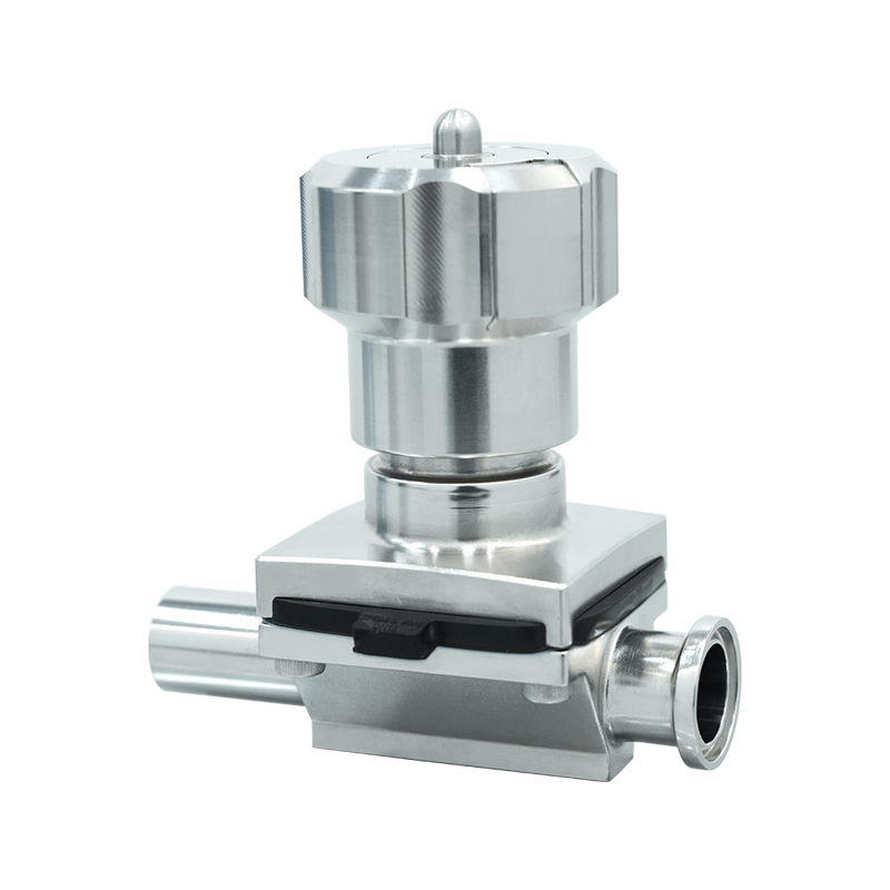
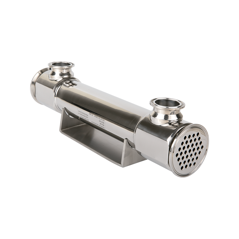
- Valve body: Bodies are manufactured from cast iron, ductile iron, stainless steel, PVC, CPVC, or PP depending on the application's pressure rating and chemical environment. The weir-type body is the most common configuration, where the diaphragm presses against a raised central ridge to close off flow. Straight-through bodies are also available for applications requiring lower pressure drop or handling of slurries where the weir profile would trap solids.
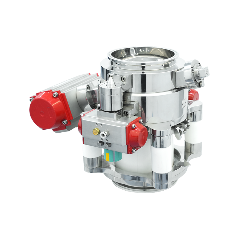
- Electric actuator: The actuator houses an electric motor, a gear reduction mechanism, and a stem assembly that translates motor rotation into the linear force needed to compress or release the diaphragm. Most actuators include position feedback via limit switches or potentiometers, allowing the control system to confirm valve status. Torque limiting protection prevents motor damage if the valve encounters an obstruction during travel.
- Control interface: Modern electric diaphragm valve actuators accept a range of control signals. On/off models respond to simple open or close commands via 24V DC or 110/220V AC power. Modulating actuators accept 4–20 mA or 0–10V DC signals for proportional positioning. Some units support HART, Profibus, Modbus, or DeviceNet protocols for integration into digital process control networks.
Industrial Applications Across Key Sectors
Electric diaphragm valves are specified across a broad range of industries, each of which exploits a different aspect of the design's capabilities. The common thread is the need for reliable, automated fluid control without contamination risk or dependence on auxiliary power sources.
Water Treatment and Wastewater Management
Municipal water treatment plants use electric diaphragm valves to control dosing of coagulants, disinfectants, and pH-adjustment chemicals. The modulating versions regulate chemical feed rates in proportion to flow sensor readings, maintaining consistent treatment chemistry without operator adjustment. In wastewater and sewage treatment facilities, electric diaphragm valves handle sludge, effluent, and chemically aggressive treatment streams. The straight-through body configuration is preferred here because the absence of a weir prevents sludge from accumulating and blocking the valve. Remote actuation allows these valves to be operated from a central SCADA system, enabling fully automated plant operation across large facilities where manual valve adjustment would be impractical.
Chemical Processing
Chemical plants require valves that resist corrosive media while providing tight shutoff and controllable flow rates. Electric diaphragm valves with PTFE-lined bodies and PTFE diaphragms are used to handle concentrated acids, alkalis, and solvents that would rapidly destroy conventional metal valve internals. The actuator's complete isolation from the process fluid means that even when the valve is handling highly corrosive or toxic media, the external control mechanism remains unaffected. This is a significant maintenance and safety advantage compared to globe or ball valves, where stem seals and packing materials are in direct contact with the process stream and represent potential leak paths.
Pharmaceutical and Food Processing
Sanitary-grade electric diaphragm valves are designed to meet the hygiene standards required by pharmaceutical manufacturing and food and beverage processing. The smooth, crevice-free internal surface of a sanitary diaphragm valve body prevents microbial growth and allows effective cleaning-in-place (CIP) and sterilization-in-place (SIP) procedures. PTFE diaphragms are used in these applications because PTFE does not shed particles, does not react with cleaning agents, and can withstand repeated steam sterilization cycles. The electric actuator enables automated cleaning sequences to be triggered by the process control system without requiring operator access to the valve.
Electric vs. Pneumatic Diaphragm Valves: A Direct Comparison
The choice between electric and pneumatic actuation for a diaphragm valve depends on the specific operational context. Both have distinct advantages, and understanding the trade-offs prevents misapplication.
| Criteria | Electric Actuator | Pneumatic Actuator |
| Infrastructure required | Electrical power only | Compressed air supply and solenoid valve |
| Response speed | Moderate (seconds) | Fast (sub-second possible) |
| Position feedback | Standard via limit switches | Requires additional positioner |
| Remote locations | Suitable — only needs power cable | Difficult — air supply lines must reach valve |
| Fail-safe options | Spring return or battery backup | Spring return on air loss |
| Modulating control | Excellent with 4–20 mA signal | Possible but requires positioner |
| Explosion-proof options | Available, higher cost | Intrinsically suitable in many cases |
Electric actuation is the practical choice for installations in remote locations where running compressed air lines would be expensive or impractical, and for systems where precise modulating control and position feedback are priorities. Pneumatic actuation remains preferred for high-cycle applications requiring very fast response times, and for hazardous area installations where intrinsically safe pneumatic systems offer a simpler compliance path than explosion-proof electrical enclosures.
Selection Criteria: Matching the Valve to the Application
Specifying an electric diaphragm valve correctly requires evaluating several parameters simultaneously. An error in any one of them — diaphragm material compatibility, pressure rating, actuator torque, or control signal type — can result in premature failure or inadequate process control.
- Fluid compatibility: Identify the chemical composition, pH, temperature range, and any abrasive or particulate content of the process fluid. Cross-reference this against the diaphragm material and body material chemical resistance tables provided by the manufacturer. A mismatch will cause diaphragm swelling, cracking, or degradation that leads to leakage or complete failure within a short operating period.
- Pressure and flow requirements: Confirm the maximum operating pressure and the required flow rate (Cv value) for the application. Diaphragm valves have inherently higher pressure drops than full-bore valve types, so the Cv must be sufficient to meet flow demands at the available differential pressure. Oversizing a diaphragm valve for throttling service leads to poor control resolution; undersizing restricts flow below process requirements.
- Actuator torque and thrust: The actuator must develop sufficient force to compress the diaphragm against the seat at the maximum operating pressure in the valve. Undersized actuators fail to close fully, resulting in seat leakage. Torque requirements increase as valve size and operating pressure increase, and the actuator datasheet must be verified against the valve manufacturer's required closing force specification.
- Control signal and power supply: Confirm whether the application requires simple on/off switching or modulating proportional control. Verify the available power supply voltage and frequency. Specify the required control signal type — 4–20 mA, 0–10V, digital fieldbus — to match the existing control system output. Mismatched signal types require additional signal converters that introduce cost and potential failure points.
- Environmental rating: Select an actuator with an IP (Ingress Protection) rating appropriate for the installation environment. Outdoor installations or wash-down areas typically require a minimum of IP65. Submersible or high-humidity environments may require IP67 or IP68. Hazardous area installations require ATEX or IECEx certification appropriate to the zone classification.
Maintenance Practices That Extend Service Life
The diaphragm is the component most subject to wear and is the primary focus of a preventive maintenance program. Inspection intervals depend on the operating conditions: a valve cycling hundreds of times per day in a corrosive chemical service will require diaphragm replacement far more frequently than a valve making only a few operations per day in clean water service. Most manufacturers publish diaphragm replacement intervals based on cycle count and service conditions, and these should be built into a scheduled maintenance program rather than relying on reactive replacement after failure. Diaphragm failure in service — particularly in a normally closed valve — can result in process fluid backflowing into the actuator housing, causing corrosion damage that requires complete actuator replacement.
The actuator mechanism requires periodic inspection of limit switch settings, which can drift over time and cause the control system to register incorrect valve positions. Gear lubrication should be checked according to the manufacturer's schedule, particularly in high-cycle applications where friction accelerates wear. Electrical connections and cable entry seals should be inspected for moisture ingress, especially in outdoor installations, as water infiltration into the actuator housing is a common cause of motor insulation failure. A well-maintained electric diaphragm valve installation combines a planned diaphragm replacement schedule with periodic actuator inspection to ensure that both the wetted flow-control components and the electrical drive system remain within their performance specifications throughout the service life of the installation.


