


Content
- 1 What Is a Manual Diaphragm Valve?
- 2 How a Manual Diaphragm Valve Works
- 3 Diaphragm Materials and Their Application Compatibility
- 4 Valve Body Materials: Matching Construction to the Process
- 5 Advantages of Manual Diaphragm Valves Over Other Valve Types
- 6 Limitations to Consider Before Specifying a Manual Diaphragm Valve
- 7 Maintenance and Diaphragm Replacement Best Practices
What Is a Manual Diaphragm Valve?
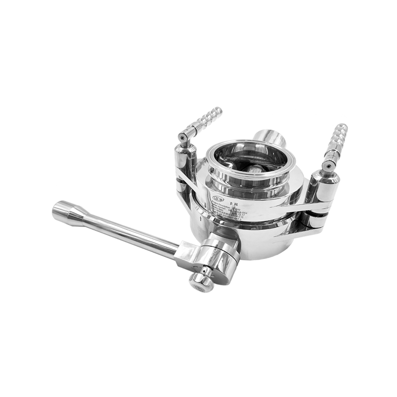
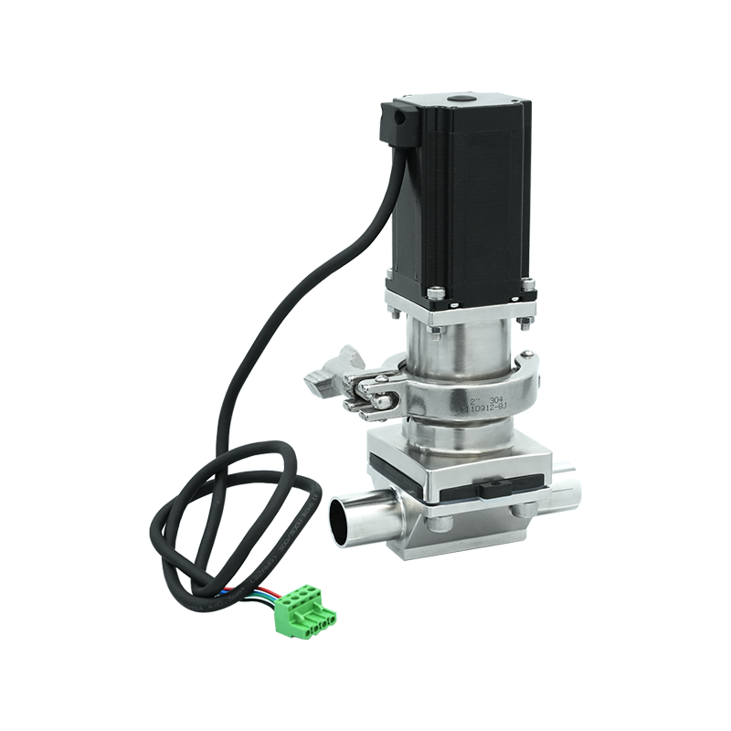
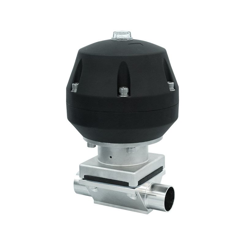
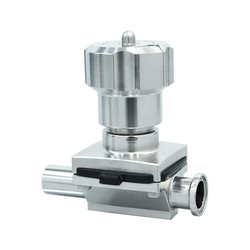
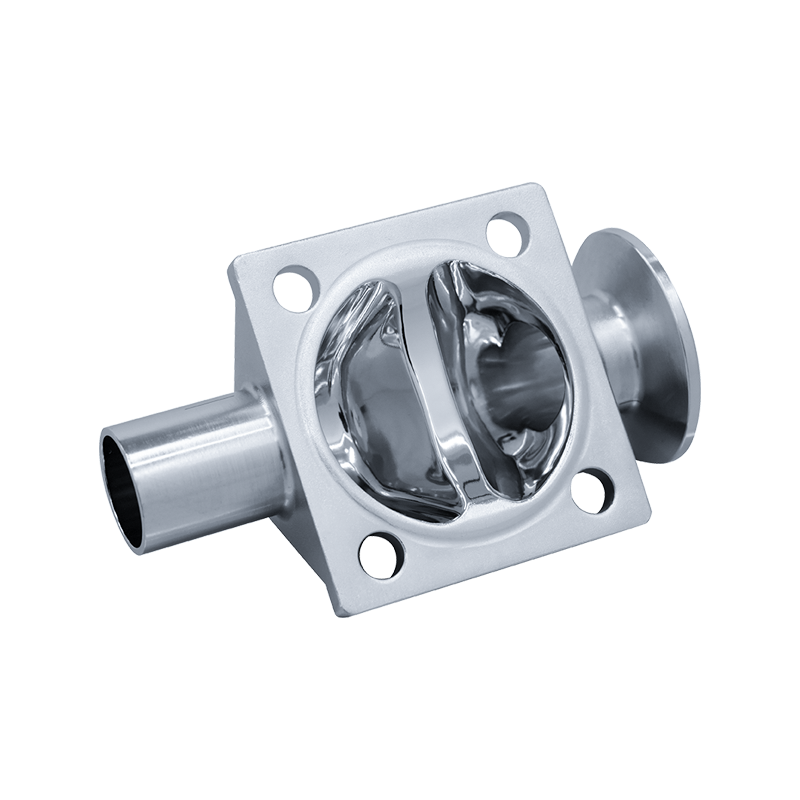
A manual diaphragm valve is a type of flow control device that uses a flexible membrane — the diaphragm — pressed against a weir or seat inside the valve body to regulate, throttle, or completely shut off fluid flow. Unlike ball valves, gate valves, or globe valves that rely on rigid metallic components moving through the fluid stream, the diaphragm valve keeps all mechanical actuating parts entirely isolated from the process fluid. This fundamental design characteristic makes it the preferred choice in applications where contamination prevention, hygienic integrity, or corrosion resistance is a primary concern.
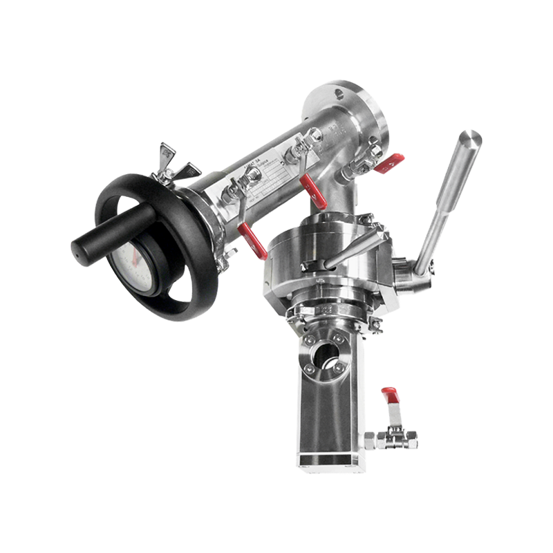
The "manual" designation refers to the method of actuation — the diaphragm is compressed or released by turning a handwheel or handle connected through a stem and compressor assembly, without any pneumatic, hydraulic, or electric actuator. Manual diaphragm valves are widely used in pharmaceutical manufacturing, food and beverage processing, chemical handling, water treatment, and semiconductor fabrication, where operators need direct, tactile control over flow without relying on external power or control signals.
How a Manual Diaphragm Valve Works
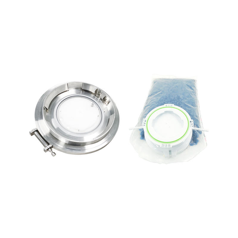
The operating principle of a manual diaphragm valve is straightforward but elegantly effective. The valve body contains a flow passage — either a weir-type raised seat or a straight-through bore — across which the flexible diaphragm is positioned. The diaphragm is clamped at its perimeter between the valve body and the bonnet, creating a pressure-tight seal that physically separates the fluid side from the mechanical side of the valve.
When the handwheel is turned in the closing direction, the stem descends, driving a compressor — a rigid disc or saddle — downward against the diaphragm. The diaphragm flexes downward and presses against the weir or seat, progressively reducing and ultimately blocking fluid flow. Turning the handwheel in the opening direction retracts the compressor, allowing the diaphragm's natural elasticity — assisted in some designs by a return spring — to lift away from the seat and restore flow. The amount of handwheel turns between fully open and fully closed positions determines the valve's throttling resolution, which is one of the key advantages of the diaphragm valve over quarter-turn alternatives.
Weir-Type vs. Straight-Through Body Design
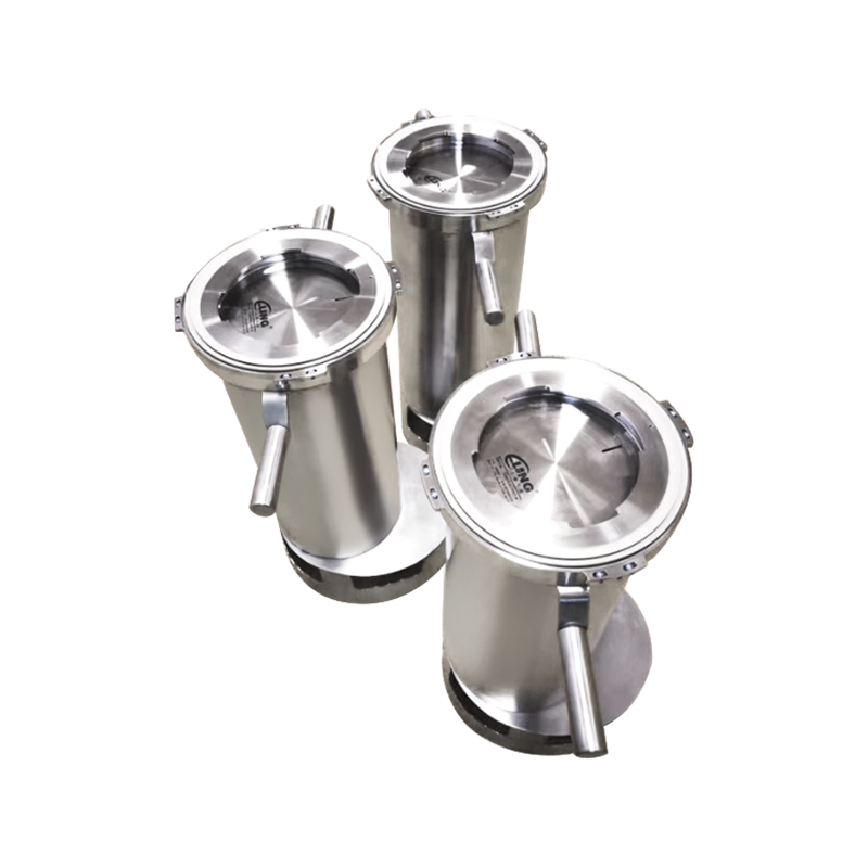
Manual diaphragm valves are manufactured in two primary body configurations that suit different application requirements. The weir-type body incorporates a raised ridge — the weir — across the flow path. The diaphragm only needs to travel a short distance to contact this weir and achieve shutoff, which reduces diaphragm flex fatigue and extends service life. Weir-type valves are the standard choice for most general industrial and hygienic applications. The straight-through or full-bore body has no weir, allowing the diaphragm to seat against the flat bottom of the valve bore. This design provides a completely unobstructed flow path when open, making it suitable for handling viscous media, slurries, or fibrous materials that would clog or accumulate against a weir.
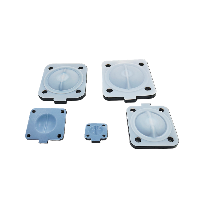
Diaphragm Materials and Their Application Compatibility
The diaphragm is the component most directly exposed to the process fluid, and its material selection has the greatest influence on the valve's chemical compatibility, temperature range, and service life. Choosing the wrong diaphragm material for the process fluid is the most common cause of premature valve failure. The following table summarizes the most widely used diaphragm materials and their key application characteristics:
| Diaphragm Material | Temperature Range | Best Suited For | Limitations |
| Natural Rubber (NR) | -20°C to +70°C | Water, dilute acids, mild alkalis | Poor resistance to oils, solvents, oxidizing agents |
| EPDM | -40°C to +120°C | Hot water, steam, dilute acids, alkalis, food processing | Not suitable for oils, hydrocarbons, or strong solvents |
| PTFE (Teflon) | -60°C to +150°C | Aggressive chemicals, concentrated acids, high-purity applications | Lower flexibility; often used as a liner over rubber backing |
| Neoprene (CR) | -20°C to +90°C | Oils, refrigerants, mild chemicals, outdoor applications | Limited resistance to strong acids and ketones |
| Viton (FKM) | -20°C to +150°C | Fuels, aromatic solvents, high-temperature chemical service | Higher cost; not suitable for ketones or certain amines |
In pharmaceutical and high-purity food applications, PTFE-lined diaphragms with an EPDM rubber backing are the industry standard. The PTFE layer contacts the process fluid, providing broad chemical inertness and meeting extractable and leachable requirements, while the rubber backing provides the flexibility and resilience needed for reliable sealing across thousands of operating cycles.
Valve Body Materials: Matching Construction to the Process
While the diaphragm handles the chemical contact challenge on the fluid side, the valve body must also resist corrosion, pressure, and temperature from the external environment and from any fluid that might contact wetted body surfaces. Manual diaphragm valves are available in a wide range of body materials to suit different service conditions.
- Stainless steel (316L): The dominant material for pharmaceutical, food, and high-purity chemical applications. 316L stainless steel offers excellent corrosion resistance, is electropolishable to Ra values below 0.4 µm for hygienic service, and meets FDA and USP Class VI material requirements. It handles a wide range of process temperatures and pressures without dimensional instability.
- Cast iron: Used in general industrial water and utility services where cost is a priority and corrosion resistance demands are moderate. Cast iron bodies are typically lined with rubber or epoxy coatings when handling mildly corrosive fluids. They are not suitable for pharmaceutical or food-grade applications.
- CPVC and PP (thermoplastics): Plastic body diaphragm valves in chlorinated polyvinyl chloride or polypropylene are widely used in chemical dosing, water treatment, and semiconductor fabrication where the process fluid would corrode metallic bodies. They offer excellent chemical resistance at a lower weight and cost than exotic alloys, but are limited in pressure and temperature ratings compared to metal bodies.
- Hastelloy C and titanium: Specified for the most aggressive chemical environments — concentrated oxidizing acids, chlorine service, or highly corrosive process streams that attack standard stainless steel. These materials carry a significant cost premium but provide reliability where no alternative material can perform adequately.
- Rubber-lined ductile iron: A cost-effective solution for large-bore valves handling abrasive slurries or corrosive water streams in mining and water treatment. The rubber lining protects the iron body from the process fluid while the iron provides structural strength at large diameters where stainless steel would be cost-prohibitive.
Advantages of Manual Diaphragm Valves Over Other Valve Types
The manual diaphragm valve's design offers a specific set of performance advantages that make it uniquely suited to certain applications, though it also has limitations that make it unsuitable for others. Understanding where diaphragm valves outperform competing technologies helps engineers and procurement specialists make well-justified selection decisions.
Zero Stem Leakage to Atmosphere
In a conventional globe or gate valve, the stem passes through packing or seals that contact the process fluid and can leak to atmosphere over time as the packing wears. In a diaphragm valve, the stem never contacts the process fluid — the diaphragm provides a permanent hermetic barrier between the fluid and the bonnet. This makes diaphragm valves the preferred choice for handling toxic, hazardous, or ultra-pure fluids where any atmospheric leakage is unacceptable.
Good Throttling Capability
The multi-turn handwheel operation of a manual diaphragm valve provides finer flow control resolution than quarter-turn ball or butterfly valves. The relationship between handwheel position and flow rate — the valve's flow characteristic — follows an approximately equal-percentage curve in weir-type designs, meaning each incremental turn of the handwheel produces a proportional percentage change in flow rather than a linear change. This characteristic makes manual diaphragm valves well suited for process applications requiring stable, adjustable flow rates rather than simple on/off service.
Hygienic Design Suitability
The smooth, crevice-free internal geometry of a well-designed diaphragm valve body — particularly in weir-type stainless steel construction — minimizes areas where product can accumulate and microorganisms can colonize. This cleanability characteristic, combined with the ability to steam-in-place (SIP) and clean-in-place (CIP) without disassembly, makes manual diaphragm valves the standard for hygienic piping systems in biopharmaceutical manufacturing, dairy processing, and beverage production.
Limitations to Consider Before Specifying a Manual Diaphragm Valve
Despite their advantages, manual diaphragm valves are not universally applicable. Being aware of their limitations avoids misapplication and premature failure in service.
- Pressure limitations: The flexible diaphragm limits the maximum working pressure the valve can handle — typically 10 to 16 bar for standard designs, compared to 40 bar or more for metallic gate or globe valves. High-pressure process lines require alternative valve types or specially reinforced diaphragm designs.
- Temperature limitations: The diaphragm material imposes an upper temperature ceiling that is lower than the body material's capability. Even PTFE-lined diaphragms are typically limited to 150°C, making diaphragm valves unsuitable for high-temperature steam or thermal oil service.
- Diaphragm fatigue over time: Repeated flexing of the diaphragm causes fatigue degradation regardless of material quality. In high-cycle applications where the valve opens and closes many times per day, diaphragm replacement becomes a regular maintenance activity that must be factored into lifecycle cost calculations.
- Not suitable for vacuum service without specific design: Standard diaphragm valves are not recommended for deep vacuum applications because the diaphragm can be drawn inward and distorted by differential pressure in the closing direction. Vacuum-rated designs with additional diaphragm support are available but must be specifically selected.
Maintenance and Diaphragm Replacement Best Practices
A structured maintenance program for manual diaphragm valves focuses primarily on monitoring diaphragm condition and replacing the diaphragm before fatigue failure occurs in service. A failed diaphragm in a process line results in cross-contamination between the fluid side and the bonnet cavity, which can introduce contamination into hygienic processes or allow hazardous fluid to escape containment in chemical service.
Replacement intervals should be established based on the manufacturer's recommended cycle life for the specific diaphragm material and operating conditions, derated appropriately for the actual temperature, pressure, and chemical exposure in the application. As a general guideline, diaphragms in continuous hygienic service are typically replaced every 12 to 24 months regardless of apparent condition, while diaphragms in low-cycle utility service may last considerably longer.
When replacing a diaphragm, the following steps ensure correct reassembly and leak-free performance:
- Isolate and depressurize the valve completely before disassembly — never attempt diaphragm replacement under pressure.
- Inspect the valve body seating surface and bonnet for corrosion, pitting, or mechanical damage that could prevent the new diaphragm from sealing correctly.
- Install the new diaphragm with the correct orientation — PTFE-faced diaphragms must be installed with the PTFE face toward the process fluid side.
- Torque bonnet bolts evenly in a cross pattern to the manufacturer's specified torque value — uneven torquing distorts the diaphragm clamping flange and creates leak paths.
- Perform a pressure test after reassembly before returning the valve to service, verifying zero leakage at both the diaphragm seal and the bonnet joint.
Keeping a stock of correctly specified replacement diaphragms on-site — organized by valve size and diaphragm material — ensures that scheduled and emergency replacements can be completed without production delays. Always use OEM or verified equivalent diaphragms rather than generic substitutes, as dimensional tolerances and material compound specifications are critical to achieving the rated performance and safety of the valve assembly.


