


Content
- 1 Understanding Sealed Sampling Valve Design and Function
- 2 Types of Sealed Sampling Valves and Selection Criteria
- 3 Installation Location and Process Connection Considerations
- 4 Proper Installation Procedures and Testing Protocols
- 5 Operating Procedures for Representative Sample Collection
- 6 Maintenance Requirements and Troubleshooting Common Issues
- 7 Regulatory Compliance and Documentation Requirements
- 8 Advanced Features and Automation Integration
Understanding Sealed Sampling Valve Design and Function
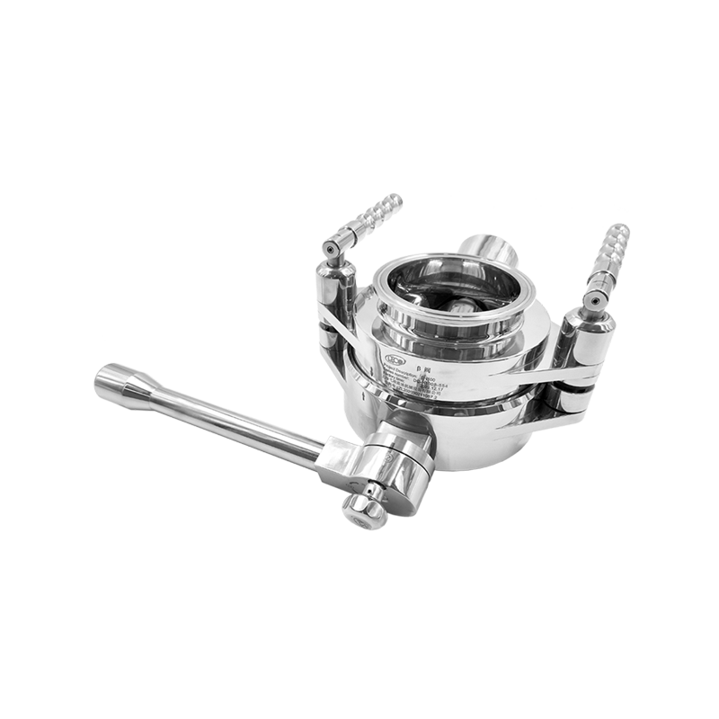
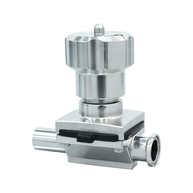
Sealed sampling valves represent specialized process equipment designed to extract representative samples from pressurized systems, hazardous fluids, or sterile environments while maintaining complete containment and preventing atmospheric exposure or contamination. These valves incorporate multiple sealing mechanisms that isolate the sample chamber from both the process stream and external environment, enabling safe collection of samples from toxic chemicals, flammable hydrocarbons, pharmaceutical products, or other materials requiring strict containment during sampling operations. The fundamental design principle involves creating a sealed cavity that can be charged with process fluid, isolated from the main system, depressurized safely, and opened for sample collection without releasing material to the atmosphere or introducing contaminants into the process stream.
The construction of sealed sampling valves typically features multiple isolation points including a process-side valve that controls flow from the main system into the sample chamber, a vent or drain valve that safely depressurizes the sample cavity before opening, and a sample extraction valve that allows controlled removal of the captured sample. Modern designs incorporate interlocking mechanisms that prevent improper valve sequencing, ensuring operators cannot open the sample extraction valve while the chamber remains pressurized or connected to the process stream. These mechanical interlocks provide critical safety protection preventing sudden release of pressurized fluids, exposure to hazardous materials, or introduction of atmospheric contamination into sensitive processes requiring sterile or inert conditions.
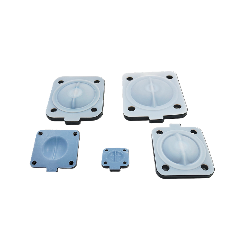
Material selection for sealed sampling valves depends on process fluid compatibility, operating temperature and pressure conditions, and regulatory requirements for specific industries or applications. Stainless steel grades including 316L remain the most common body material due to broad chemical compatibility, excellent corrosion resistance, and acceptance across pharmaceutical, food processing, and chemical manufacturing applications. Specialized applications may require exotic alloys such as Hastelloy for highly corrosive chemicals, titanium for chlorine service, or specialized plastics like PTFE or PEEK for ultrapure applications in semiconductor manufacturing. Sealing components including O-rings, gaskets, and stem seals require particular attention to material compatibility, with options ranging from standard elastomers for benign services to specialized fluoropolymers, graphite, or metal seals for extreme chemical or temperature conditions.
Types of Sealed Sampling Valves and Selection Criteria
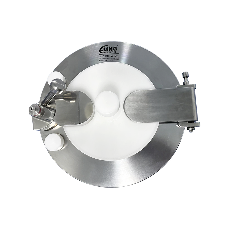
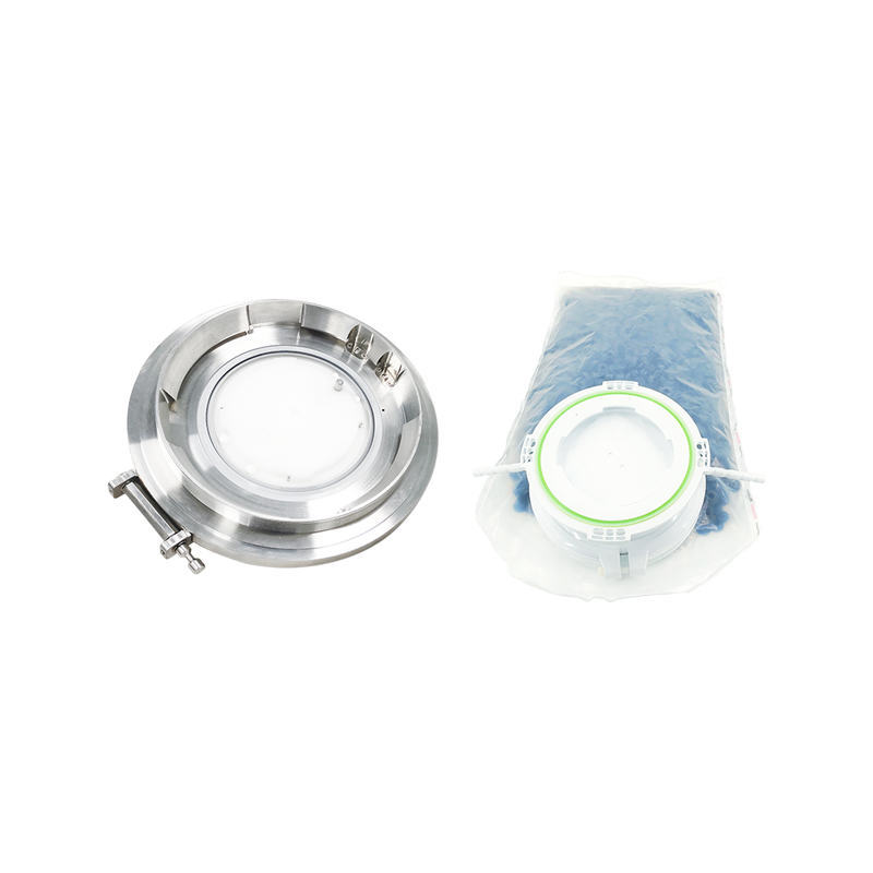
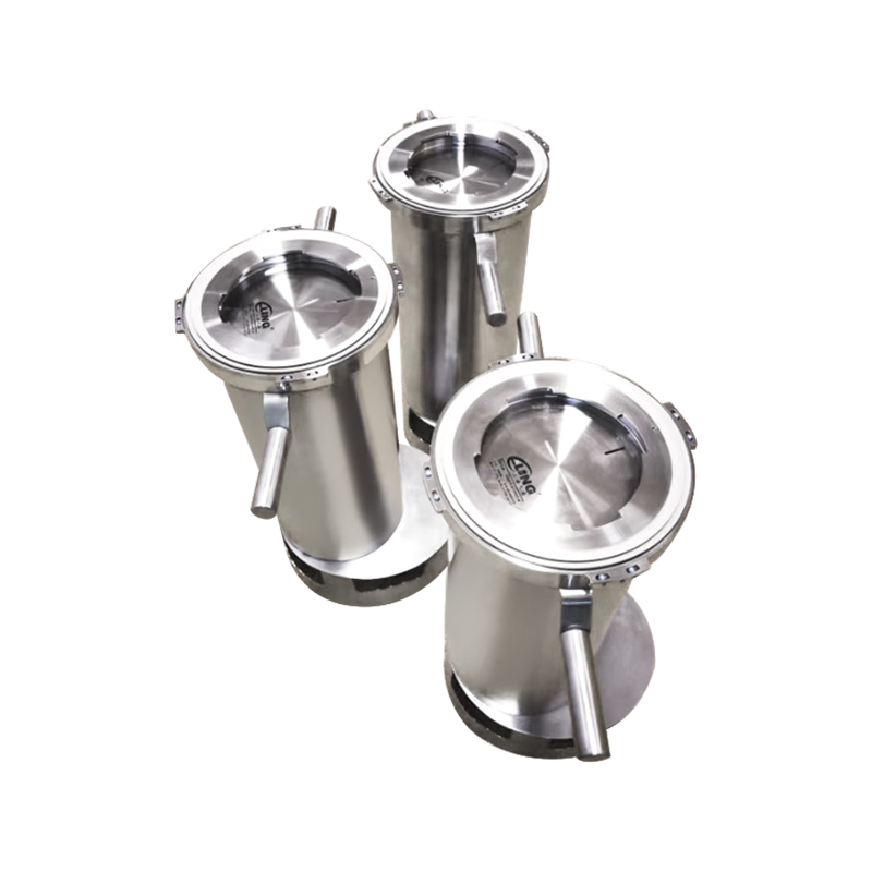
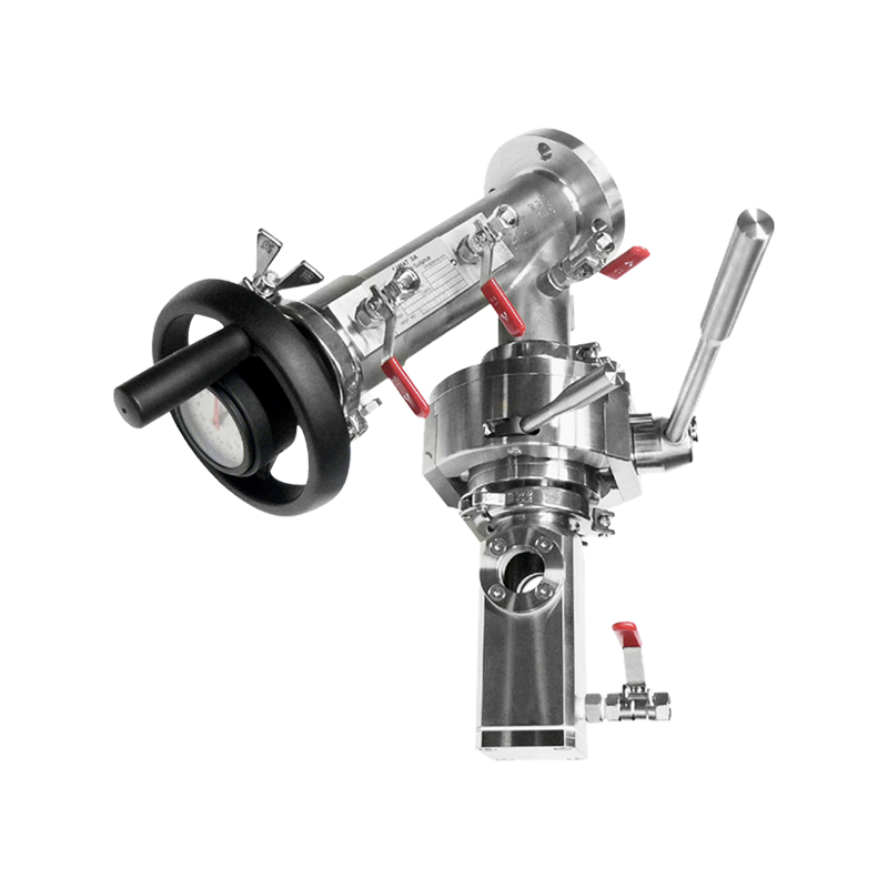
Closed-loop sampling valves represent the most comprehensive containment design, featuring integrated collection bottles or containers that attach directly to the valve assembly, creating a completely sealed transfer path from process to sample container without atmospheric exposure. These systems prove essential for volatile organic compounds, toxic materials, or sterile pharmaceutical products where any atmospheric contact would compromise sample integrity, create safety hazards, or violate regulatory requirements. The closed-loop design typically incorporates quick-connect fittings that allow pre-evacuated sample bottles to be attached and filled under vacuum, or pressurized collection vessels that equilibrate with the sample chamber pressure during transfer, eliminating sample flashing or composition changes that might occur with pressure reduction.
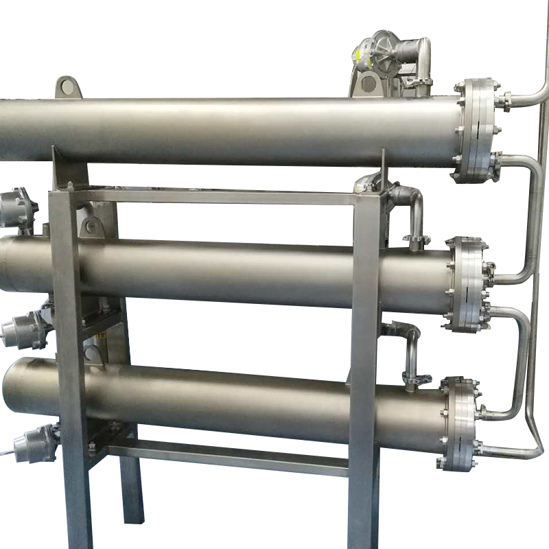
Cylinder-style sampling valves utilize a cylindrical sample chamber positioned between inlet and outlet valves, with the chamber sized to provide adequate sample volume for required analytical testing while minimizing waste of valuable or hazardous process materials. These valves typically feature a three-valve configuration including process inlet valve, process outlet valve, and sample discharge valve, with operation sequences that first flush the sample chamber with fresh process fluid to ensure representative samples, then isolate and depressurize the chamber before sample extraction. The cylinder design offers flexibility for various sample volumes ranging from a few milliliters to several liters, with chamber sizing selected based on analytical requirements and the number of tests to be performed on each sample.
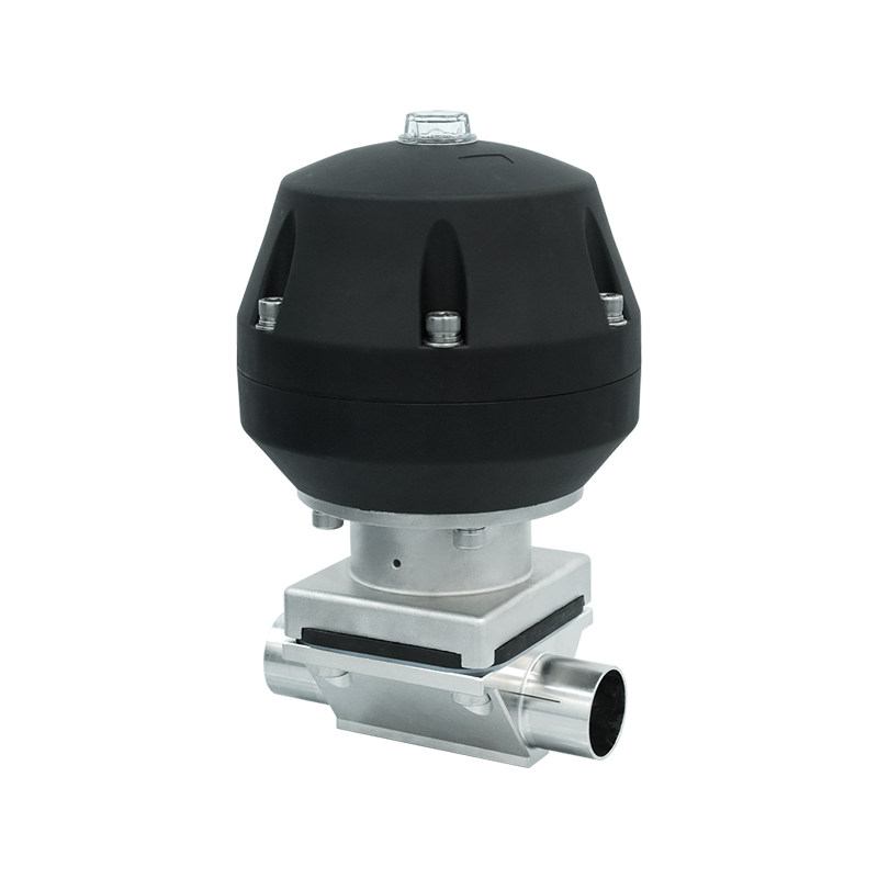
Piston-style sampling valves employ a movable piston within the sample chamber that allows precise volume control and minimizes sample exposure to valve internal surfaces, reducing cross-contamination between successive samples. The piston mechanism pushes previous sample material completely out of the chamber during flushing operations, preventing mixing or carryover that could compromise sample representativeness. This design proves particularly valuable for applications requiring small, precisely controlled sample volumes or when sampling materials prone to coating or adhering to chamber surfaces. However, piston seals represent additional potential leak paths requiring maintenance attention and material compatibility consideration for aggressive process fluids.
Sampling Valve Configuration Comparison
| Valve Type | Containment Level | Sample Volume Control | Best Applications |
| Closed-loop | Maximum | Container dependent | Volatile, toxic, sterile products |
| Cylinder-style | High | Fixed chamber size | General chemical sampling |
| Piston-style | High | Precise, adjustable | Small volumes, clean samples |
| Quick-connect | Variable | Bottle dependent | Frequent sampling, multiple points |
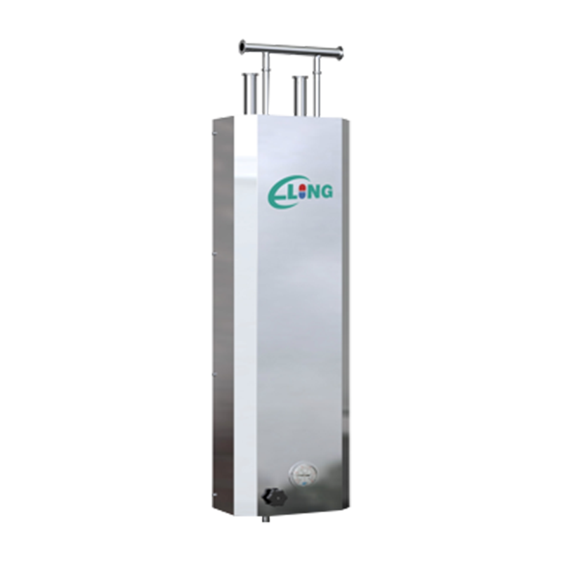
| Integrated cooler | High | Chamber size | High-temperature processes |
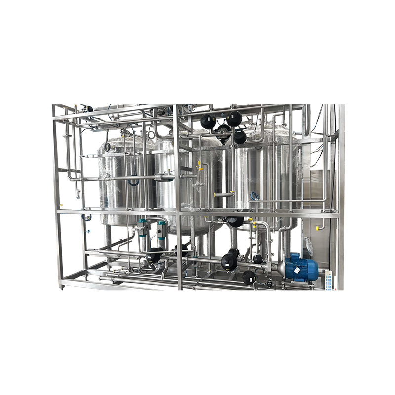
Installation Location and Process Connection Considerations
Selecting appropriate sampling locations within process systems critically affects sample representativeness, with ideal locations providing well-mixed, single-phase flow that accurately reflects bulk process conditions rather than localized anomalies or phase separations. Install sampling connections at points where turbulent flow ensures thorough mixing, avoiding dead legs, low-velocity zones, or areas where settling, stratification, or phase separation might create non-representative conditions. For liquid sampling, position connections on the side of horizontal pipes rather than at the top where vapor might accumulate or bottom where solids could settle, ensuring the sample probe draws from the well-mixed central flow region rather than boundary layers or separated phases.
Process connection design must minimize dead volume and provide adequate flow velocity through the sampling system to ensure sample freshness and representativeness while preventing material degradation, phase changes, or composition shifts during sample extraction. Use short, direct connection paths from the main process line to the sampling valve, avoiding unnecessary fittings, valves, or extended tubing runs that create stagnant zones where material properties might change before reaching the sampling point. Connection tubing diameter should balance competing requirements for minimal dead volume favoring small diameters against adequate flow velocity for rapid sample chamber flushing requiring larger sizes, with typical installations using one-quarter to one-half inch tubing for most liquid sampling applications.
Sampling valve orientation affects operation ergonomics, maintenance accessibility, and proper functioning of certain valve designs requiring specific installation positions. Mount valves in locations providing clear access for operation, sample collection, and maintenance activities without requiring ladders, awkward postures, or interference from adjacent equipment. Vertical mounting with sample extraction point at the bottom facilitates complete drainage during sampling operations and cleaning procedures, though horizontal installations may prove acceptable for many valve designs. Ensure adequate clearance exists below sample extraction points to accommodate collection containers, with space planning accounting for the largest sample bottles or vessels used in normal operations.
Proper Installation Procedures and Testing Protocols
Process connection installation begins with thorough cleaning of pipe taps, sampling valve ports, and all tubing or fittings that will contact process fluids, removing installation debris, cutting oils, or protective coatings that might contaminate samples or interfere with valve operation. For pharmaceutical or food processing applications, cleaning protocols should follow validated procedures appropriate for the specific product contact materials and regulatory requirements, with documentation confirming cleanliness before system startup. Install tubing using proper compression fitting techniques that achieve leak-tight seals without over-tightening that can damage ferrules or tubing, following manufacturer torque recommendations or using pull-testing to verify adequate grip without deformation.
Pressure testing sealed sampling valve installations verifies leak integrity before introducing hazardous or valuable process materials, typically using inert gases or water at pressures exceeding maximum operating pressure by specified safety factors. Apply test pressure gradually while monitoring all connections, valve body joints, and sealing points for leakage indicated by pressure decay, bubble formation in leak detection solution, or audible hissing from escaping gas. Particular attention should focus on threaded connections, compression fittings, and valve stem seals representing common leak paths in sampling systems. Document test pressures, hold times, and leak test results as part of installation quality records, particularly for applications subject to regulatory oversight or quality management system requirements.
Functional testing demonstrates proper valve operation, interlock functionality, and complete sample chamber isolation before placing the system in service with actual process materials. Verify that valve handles or actuators operate smoothly through their full range of motion without binding or excessive force requirements that might indicate improper installation or component defects. Test interlock mechanisms by attempting improper operation sequences such as opening sample extraction valves while the chamber remains pressurized, confirming that mechanical or electrical interlocks prevent unsafe operations. For sampling valves equipped with automatic purge or flush systems, verify proper sequencing, flow rates, and timing to ensure adequate sample chamber conditioning before sample collection.
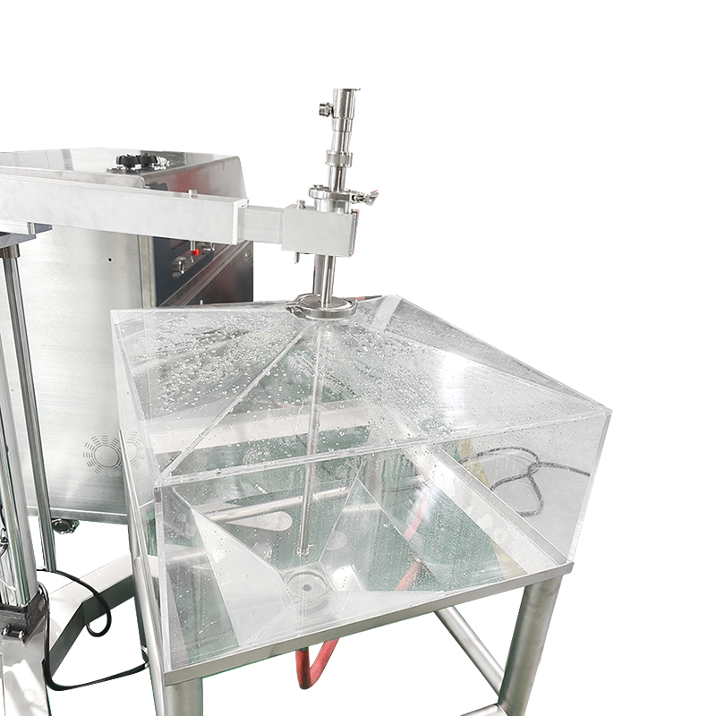
Operating Procedures for Representative Sample Collection
Proper sampling valve operation sequences ensure collection of representative samples while maintaining safety and process integrity throughout the sampling procedure. The typical sequence begins with opening the process inlet valve to charge the sample chamber with fresh process fluid, followed by opening the outlet valve to establish flow-through flushing that purges stagnant material and conditions the chamber to process temperature and composition. Flush volumes should equal at least five to ten times the sample chamber volume to ensure complete displacement of stagnant material and achievement of equilibrium conditions matching the main process stream. For critical applications or when sampling parameters differ significantly from ambient conditions, extended flushing using twenty or more chamber volumes may be necessary to ensure representative samples.
Sample isolation procedures involve closing both inlet and outlet valves to capture process fluid within the sample chamber, followed by controlled depressurization through dedicated vent or drain valves before opening the sample extraction port. Never attempt to open sample extraction valves while the chamber remains at process pressure, as sudden pressure release creates safety hazards from material spraying, potential ignition sources from static discharge, or sample flashing that changes composition. Depressurization should occur slowly through appropriate relief paths to safe disposal locations, with vent streams directed to closed drain systems, vapor recovery equipment, or scrubbers as required for hazardous materials. Allow adequate time for pressure equalization before opening extraction valves, verifying zero pressure through installed pressure indicators or manual pressure checks if gauge indication proves unavailable.
Sample extraction techniques vary based on sample properties and analytical requirements, with liquid samples typically drained by gravity into collection containers while gas samples may require vacuum extraction or displacement into pre-evacuated vessels. Position collection containers to capture samples completely without spillage, using funnels or direct-connect fittings as appropriate for the sample valve design. Avoid sample contact with atmospheric moisture or oxygen for materials sensitive to contamination, using inert gas purging of collection containers or closed transfer systems maintaining containment throughout the sampling process. Label samples immediately with unique identifiers, collection date and time, process conditions during sampling, and any special handling requirements, ensuring traceability throughout the analytical process.
Safe Sampling Operation Sequence
- Verify all sampling equipment including collection containers, personal protective equipment, and disposal provisions are prepared and positioned before initiating sampling operations
- Open process inlet valve slowly to charge sample chamber while monitoring for leaks or unexpected pressure surges indicating valve malfunction or improper installation
- Open outlet valve to establish flow-through flushing, maintaining sufficient flow to purge chamber completely while avoiding excessive velocities that might cause erosion or sample flashing
- Close inlet and outlet valves in proper sequence to isolate sample within chamber, verifying complete closure through visual indication or valve position feedback systems
- Open vent or drain valve to depressurize sample chamber slowly, directing discharge to appropriate containment systems and monitoring pressure indicators until reaching atmospheric pressure
- Open sample extraction valve only after confirming complete depressurization, collecting sample into prepared containers while minimizing atmospheric exposure or contamination
- Close all valves after sample collection, dispose of purge and waste materials properly, and document sampling activities including any anomalies observed during operations
Maintenance Requirements and Troubleshooting Common Issues
Regular maintenance of sealed sampling valves prevents leakage, ensures operational reliability, and maintains sample representativeness throughout the valve service life. Inspection intervals should address both external visual checks performed during routine plant operations and detailed internal inspections requiring valve disassembly conducted during scheduled maintenance outages. External inspections examine valve bodies, connections, and actuators for visible leakage, corrosion, mechanical damage, or handle operation difficulties indicating developing problems requiring attention. Check process connections for weeping or staining suggesting incipient leaks, examine valve stems for packing leakage, and verify interlock mechanisms operate freely without binding or excessive resistance.
Stem seal and packing replacement represents the most common maintenance activity for sealed sampling valves, addressing normal wear from repeated operation and material degradation from chemical exposure or temperature cycling. Replacement procedures typically require isolating the valve from process pressure, removing stem handles or actuators, and disassembling packing glands to access worn sealing elements. Install new packing using materials compatible with process fluids and operating conditions, stacking packing rings in proper orientation and quantities specified by valve manufacturers. Tighten packing glands to achieve seal without excessive stem friction that impairs operation, using graduated tightening approaches that compress packing incrementally while checking stem operation after each adjustment.
Valve seat refurbishment becomes necessary when leakage testing reveals shutoff deterioration beyond acceptable limits for the specific application. Minor seat damage may be repairable through lapping procedures using fine abrasive compounds and specialized lapping tools that restore smooth sealing surfaces, though excessive lapping removes base material and may compromise long-term reliability. Severe seat damage including deep scratches, corrosion pitting, or erosion requires complete seat replacement, with procedures varying significantly between valve designs ranging from simple threaded seat rings to seats requiring specialized tools and press-fitting techniques. After seat repair or replacement, conduct leak testing to verify restored shutoff capability before returning valves to service.
Regulatory Compliance and Documentation Requirements
Pharmaceutical manufacturing applications require sealed sampling systems meeting current Good Manufacturing Practice regulations that mandate contamination prevention, equipment qualification, and comprehensive documentation of sampling procedures and results. Sampling valve installations must be designed, installed, and maintained to prevent product contamination while enabling collection of samples demonstrating batch conformance to established specifications. Equipment qualification protocols include installation qualification verifying proper installation according to specifications, operational qualification demonstrating correct operation under anticipated conditions, and performance qualification confirming the sampling system consistently provides representative samples meeting analytical requirements.
Chemical process safety regulations including OSHA Process Safety Management and EPA Risk Management Program requirements may classify sealed sampling systems as critical equipment requiring mechanical integrity programs ensuring reliable operation throughout the equipment lifecycle. Mechanical integrity programs mandate written maintenance procedures, trained personnel performing maintenance and inspection activities, documentation of all maintenance and repairs, and quality assurance protocols verifying that maintenance work meets defined standards. Sampling valve maintenance records should document inspection findings, parts replacements, leak test results, and functional verification, creating audit trails demonstrating ongoing equipment integrity and compliance with applicable safety regulations.
Environmental regulations governing emissions of volatile organic compounds or hazardous air pollutants may require sealed sampling systems demonstrating leak-free operation through periodic leak detection and repair programs. EPA Method 21 protocols specify procedures for detecting fugitive emissions from valves and other equipment components using portable hydrocarbon analyzers, with defined screening concentrations triggering repair requirements. Sampling valves exceeding leak thresholds must be repaired within specified time frames and retested to verify successful repair, with documentation maintained demonstrating compliance with applicable leak detection and repair program requirements. Closed-loop sampling systems that eliminate atmospheric emissions may receive regulatory credit reducing leak detection and repair obligations compared to conventional sampling methods involving atmospheric exposure.
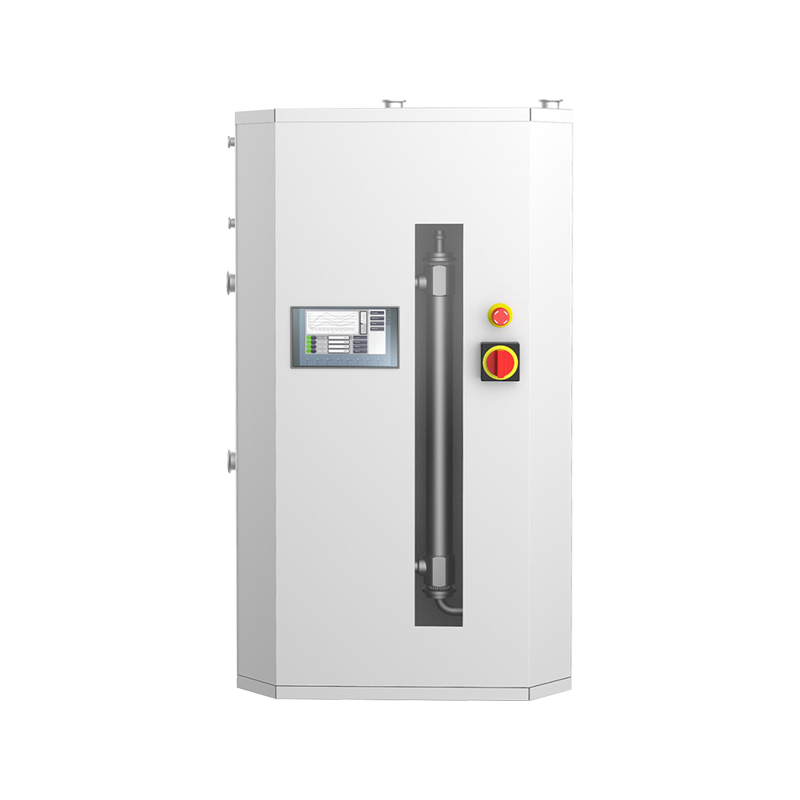
Advanced Features and Automation Integration
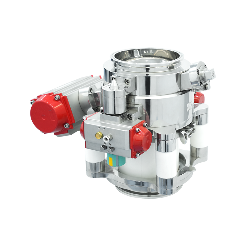
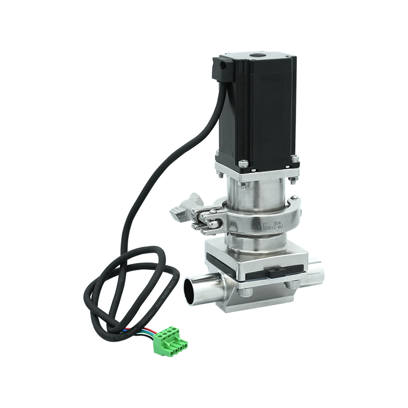
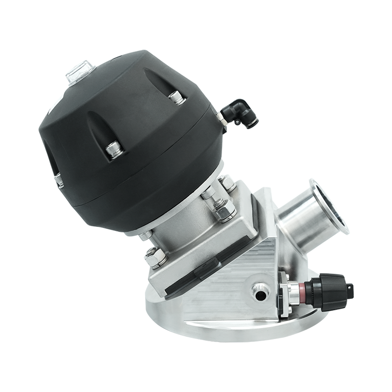
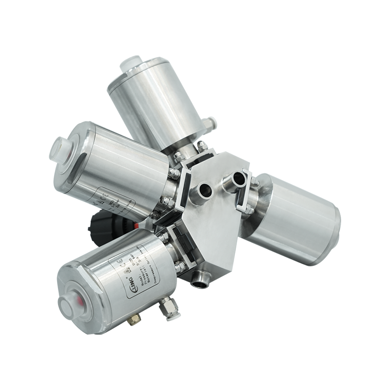
Automated sampling systems incorporate pneumatic or electric actuators that execute valve operation sequences under programmable logic controller supervision, eliminating manual operations while ensuring consistent procedures and improved operator safety. Automation proves particularly valuable for hazardous material sampling, frequent sampling programs requiring operator efficiency, or remote locations where manual sampling creates logistical challenges. Actuator selection must provide adequate force and speed for reliable valve operation while accommodating process pressures and valve sizes, with fail-safe designs ensuring valves move to predetermined safe positions upon power or signal loss.
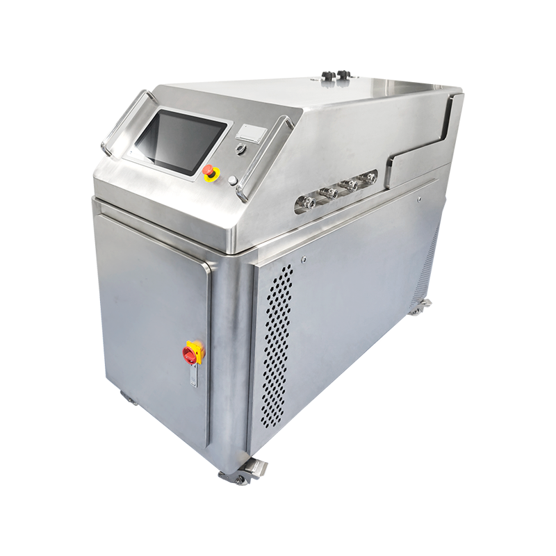
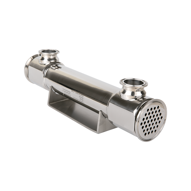
Sample conditioning systems integrated with sealed sampling valves provide temperature control, pressure reduction, or phase separation ensuring analytical instruments receive samples in proper condition for accurate measurement. Cooling systems reduce high-temperature process samples to ranges compatible with analytical equipment and sample container materials, using heat exchangers, refrigeration systems, or thermoelectric coolers depending on temperature differentials and cooling capacity requirements. Pressure reduction through back-pressure regulators or controlled venting systems prevents sample flashing and composition changes when extracting samples from high-pressure processes into atmospheric collection vessels.
Online analytical systems eliminate manual sampling entirely by continuously circulating process fluid through sealed measurement cells, with sample conditioning valves managing flow, temperature, and pressure to maintain representative conditions at analyzer sensing elements. These systems provide real-time composition data enabling advanced process control while eliminating operator exposure to hazardous materials and reducing sample collection labor. Sample conditioning valve manifolds direct process streams through filters, coolers, and pressure regulators before reaching analytical instruments, with return streams recycled to the process or directed to safe disposal. Proper design of online sampling systems addresses response time requirements, sample loop dead volume, and conditioning equipment selection to ensure measurements accurately reflect current process conditions without excessive lag or composition changes during sample transport and conditioning.


