


Content
- 1 Understanding Pneumatic Diaphragm Valve Components and Operation
- 2 Pre-Installation Planning and Site Preparation
- 3 Valve Body Installation and Connection Procedures
- 4 Pneumatic Actuator Mounting and Air Line Connection
- 5 Control Air System Integration and Testing
- 6 Commissioning Procedures and Functional Testing
- 7 Common Installation Problems and Corrective Actions
- 8 Documentation and Maintenance Planning
Understanding Pneumatic Diaphragm Valve Components and Operation
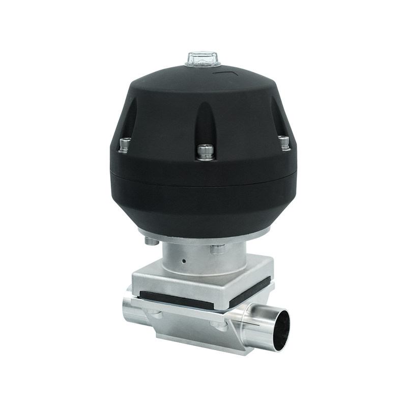
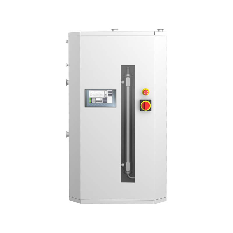
Pneumatic diaphragm valves operate through compressed air pressure acting on a flexible diaphragm that controls fluid flow through the valve body, offering precise control and reliable shutoff in diverse industrial applications. The fundamental design separates the process media from the actuating mechanism through an elastomeric or PTFE diaphragm, preventing contamination of sensitive fluids while protecting internal components from corrosive or abrasive substances. This isolation characteristic makes pneumatic diaphragm valves particularly valuable in pharmaceutical manufacturing, food processing, chemical handling, and semiconductor fabrication where product purity and contamination prevention represent critical operational requirements.
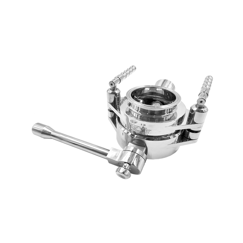
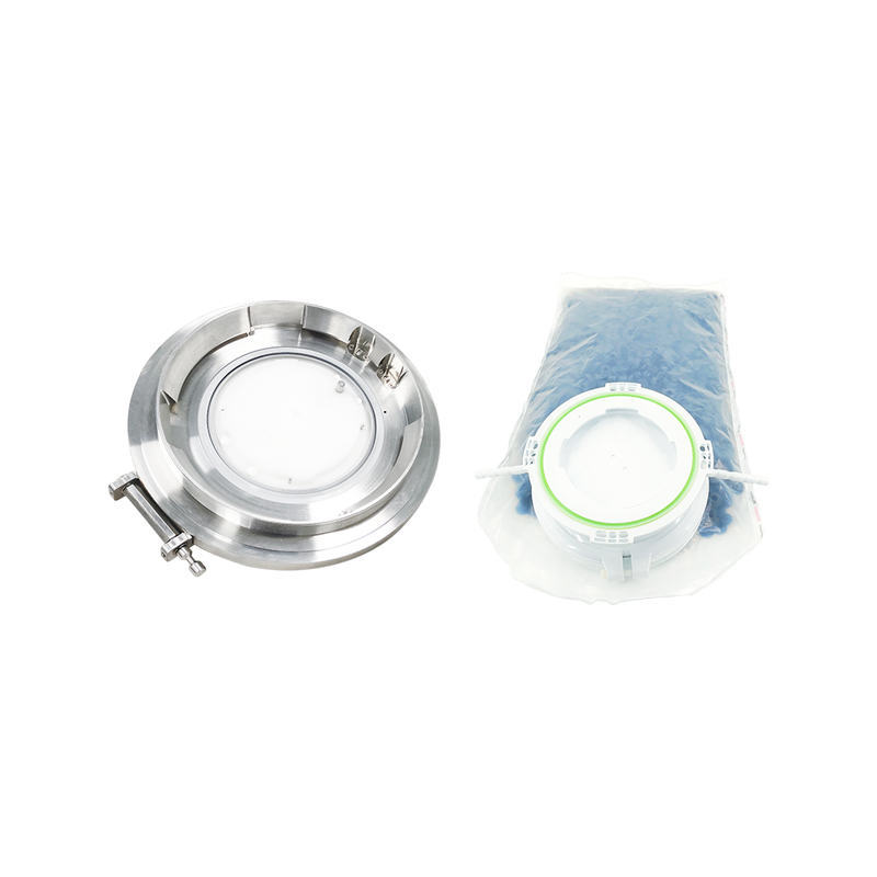
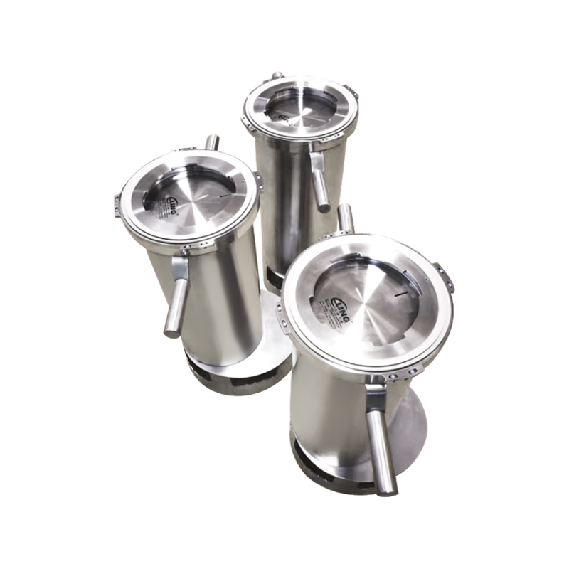
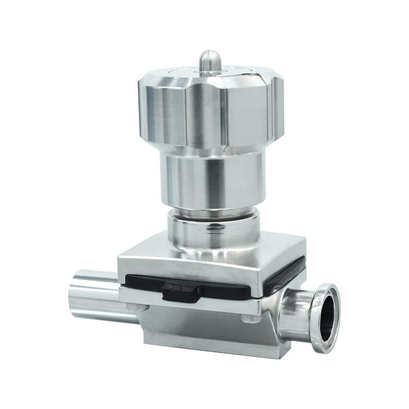
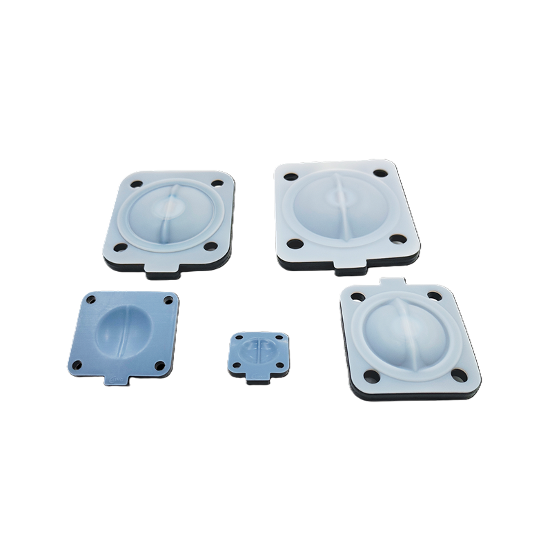
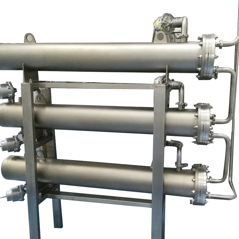
The valve body houses the flow passage and diaphragm seat, typically constructed from stainless steel, PVC, PVDF, or other materials selected based on chemical compatibility with the process fluid and operating temperature requirements. The diaphragm itself clamps between the valve body and bonnet assembly, creating a seal that prevents fluid migration into the actuator chamber while allowing the compressor or stem to transmit actuating force from the pneumatic actuator to the diaphragm. Material selection for the diaphragm proves critical, with options including EPDM for general water service, Viton for chemical resistance, PTFE for extreme chemical compatibility, and specialized compounds for high-temperature applications or specific chemical exposures.
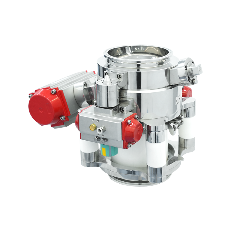
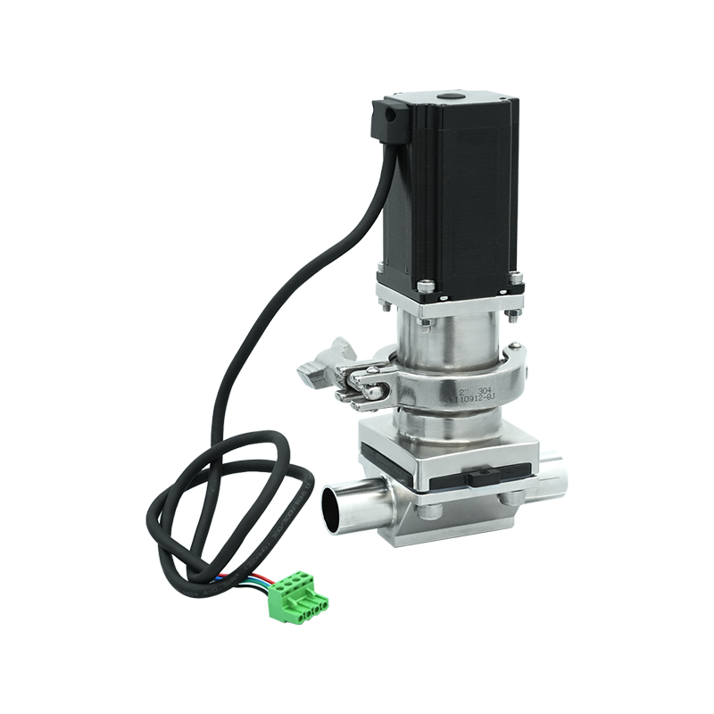
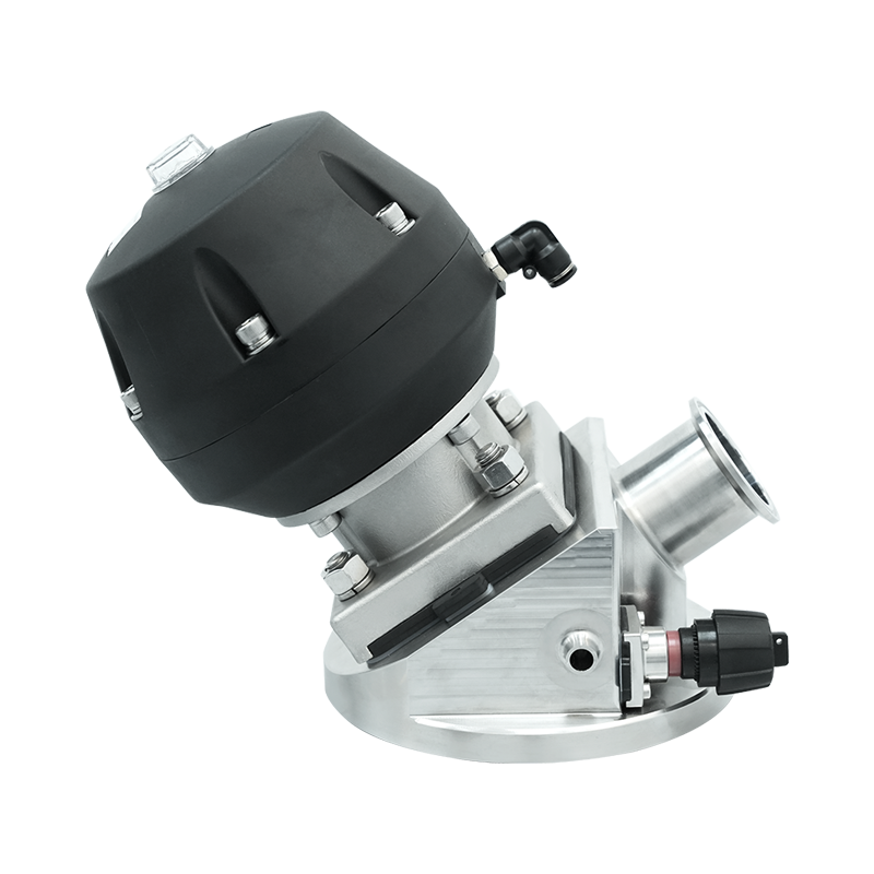
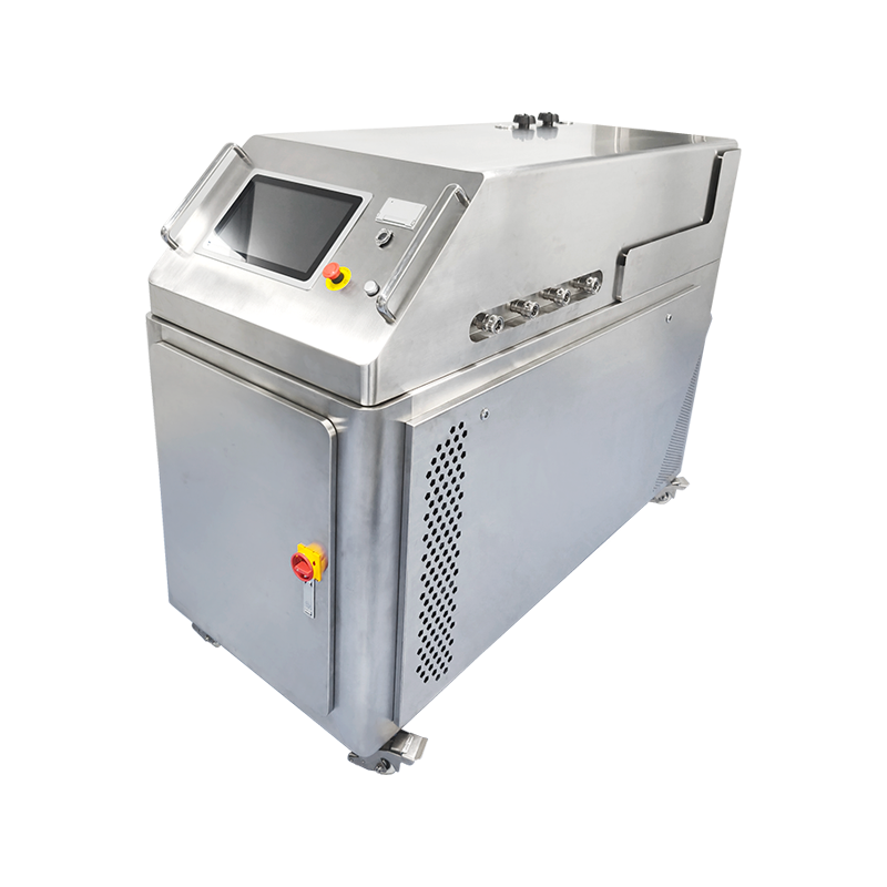
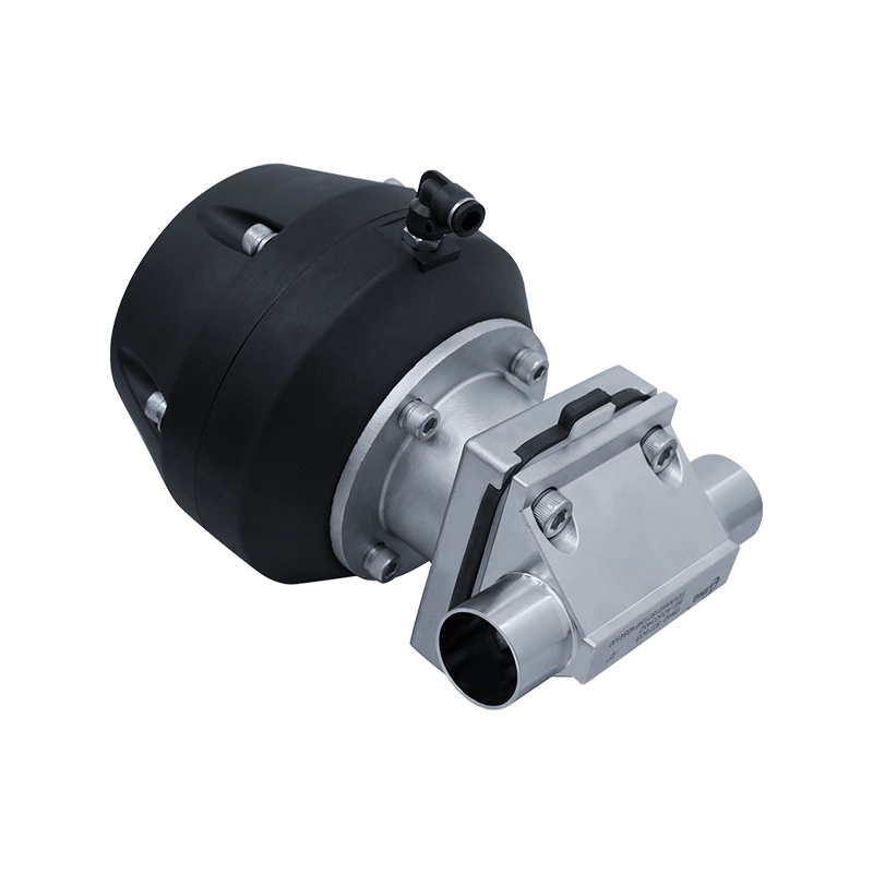
The pneumatic actuator converts compressed air pressure into mechanical force that opens or closes the valve, with actuator sizing determined by the required stem force to overcome fluid pressure, diaphragm stiffness, and any process conditions affecting valve operation. Linear actuators provide proportional control through varying air pressure that positions the diaphragm at intermediate points between fully open and fully closed, enabling precise flow regulation in automated process control systems. Spring-return actuators incorporate internal springs that automatically drive the valve to a predetermined safe position upon air pressure loss, providing fail-safe operation essential for emergency shutdown systems and applications requiring predictable failure mode behavior.
Pre-Installation Planning and Site Preparation
Successful pneumatic diaphragm valve installation begins with comprehensive planning that addresses piping configuration, actuator accessibility, instrument air requirements, and environmental conditions at the installation location. Review process and instrumentation diagrams to verify the specified valve size, pressure rating, material construction, and actuation requirements match the actual application conditions, confirming that the selected valve can handle the maximum operating pressure, temperature extremes, and chemical exposures anticipated during normal and upset conditions. Discrepancies between specifications and field conditions should be resolved before installation proceeds, as installing incompatible valves creates safety hazards, operational problems, and potential equipment damage.
Piping alignment and support requirements demand attention during pre-installation planning, as misaligned pipes impose mechanical stress on valve bodies that can cause leakage, premature failure, or operational difficulties. The piping system should include adequate supports on both sides of the valve location, preventing the valve from supporting pipe weight that would create stress on the valve body or connections. Verify that upstream and downstream piping follows the same nominal size as the valve, or confirm that proper reducers are available if size transitions occur near the valve location. Attempting to compensate for misaligned piping by over-tightening valve connections creates stress concentrations that crack valve bodies, particularly with brittle materials like PVC or glass-lined components.
Instrument air supply requirements include verifying adequate pressure, flow capacity, and air quality to operate the pneumatic actuator reliably throughout its service life. Standard pneumatic actuators typically require forty to one hundred pounds per square inch air pressure depending on actuator design and valve size, with air supply systems maintaining pressure at least twenty percent above minimum actuator requirements to ensure reliable operation despite supply pressure variations. Air quality specifications generally mandate removal of moisture, oil, and particulates through filtration and drying equipment, preventing actuator corrosion, seal degradation, and operational problems from contaminated air supply. Installing a dedicated filter-regulator unit near the valve location provides localized air conditioning and pressure regulation specific to that valve's requirements.
Pre-Installation Checklist
- Verify valve specifications match process requirements including size, pressure rating, material compatibility, and end connection type before removing from packaging or preparing for installation
- Inspect valve and actuator for shipping damage including dents, cracks, or bent components, and verify all accessories including positioners, limit switches, or solenoid valves are present and undamaged
- Confirm piping is clean, properly supported, and aligned within acceptable tolerances, with gasket surfaces free from debris, damage, or irregularities that might compromise sealing
- Verify instrument air supply meets pressure, flow, and quality requirements with appropriate filtration, regulation, and moisture removal equipment installed and functioning properly
- Ensure adequate clearance exists for actuator operation, maintenance access to diaphragm and bonnet assembly, and future replacement of wear components without extensive piping disassembly
Valve Body Installation and Connection Procedures
Proper valve orientation ensures optimal performance and prevents operational problems, with most diaphragm valves designed for specific installation positions indicated by flow direction arrows cast or stamped on the valve body. Installing valves backward reverses the intended flow pattern across the diaphragm, potentially causing premature wear, reduced shutoff capability, or control instability in throttling applications. The actuator orientation also requires consideration, with pneumatic actuators typically mounted vertically above the valve body to prevent moisture accumulation in actuator chambers and allow proper drainage of any condensation that forms during operation.
Flange connection installation for flanged diaphragm valves involves careful gasket selection, bolt tightening sequences, and torque control to create uniform compression around the entire flange circumference without over-stressing the valve body. Select gaskets compatible with both the process fluid and the flange facing material, with full-face gaskets recommended for plastic or glass-lined valve bodies to distribute bolt loads across the entire flange face rather than concentrating stress at the raised face. Install flange bolts finger-tight initially, then apply torque in a star pattern working from opposite bolts progressively toward adjacent fasteners, completing multiple tightening passes with gradually increasing torque until reaching the specified final value appropriate for the flange material and rating.
Threaded connection installation requires thread sealant or tape application that prevents leakage without contaminating the process stream or making future disassembly difficult. Apply PTFE tape or appropriate thread sealant to male threads only, wrapping tape in the direction that tightening motion compresses rather than unwraps the tape from the threads. Thread engagement should begin easily by hand, with resistance indicating cross-threading, damaged threads, or foreign material requiring correction before applying wrenches. Tighten threaded connections to recommended torque values using proper wrench sizes that engage flats fully, avoiding adjustable wrenches or pipe wrenches that can damage valve bodies or deform connection threads through excessive or improperly distributed force.
Pneumatic Actuator Mounting and Air Line Connection
Actuator mounting to the valve bonnet requires verifying proper alignment between the actuator stem and the valve compressor or diaphragm plate, ensuring force transmission occurs concentrically without side loading that causes binding or premature wear. Most pneumatic diaphragm valves utilize standardized actuator mounting patterns conforming to industry standards such as VDI/VDE 3845 or ISO 5211, allowing interchangeability between actuators from different manufacturers. However, verify mounting bolt hole patterns, stem connections, and overall dimensions match before attempting installation, as dimensional variations between supposedly compatible components can prevent proper assembly or create operational problems despite successful physical installation.
Securing the actuator to the valve involves tightening mounting bolts to specified torque values in a cross-pattern sequence that distributes clamping force uniformly around the mounting flange. Under-tightening allows movement between actuator and valve that damages mounting surfaces and creates alignment problems, while over-tightening can crack plastic valve bonnets or deform mounting flanges on metal components. Most manufacturers specify mounting bolt torques in their installation instructions, with values varying based on bolt size, material, and the specific valve-actuator combination being installed. In the absence of specific torque specifications, apply standard torque values for the bolt grade and size being used, exercising particular caution with plastic components that tolerate lower stress than metal assemblies.
Air line connections to the actuator require appropriate fittings, tubing materials, and connection methods that prevent leakage while allowing future disconnection for maintenance or actuator replacement. Plastic or nylon tubing sized appropriately for the actuator port connections provides flexible connections that accommodate minor actuator movement while resisting kinking or flow restriction. Push-to-connect fittings enable rapid, reliable connections without requiring thread sealants or special tools, though proper tubing cutting and insertion techniques prove essential for leak-free performance. Cut tubing with appropriate cutters that produce square, clean cuts without deforming the tube end, then insert tubing fully into the fitting until it bottoms against the internal stop, verifying secure engagement by attempting to pull the tubing free without releasing the fitting collar.
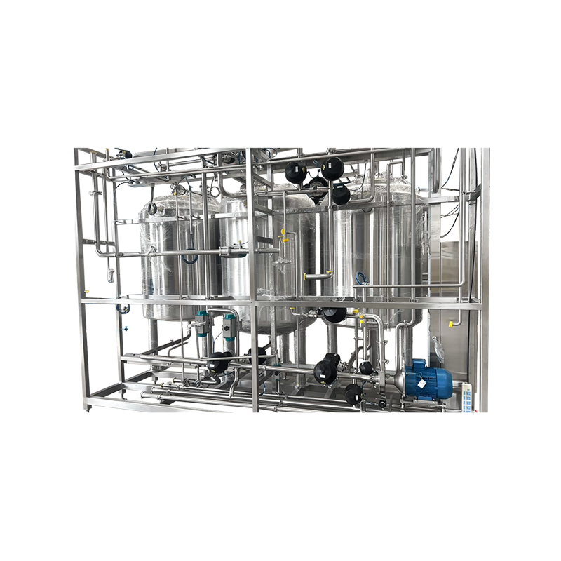
Control Air System Integration and Testing
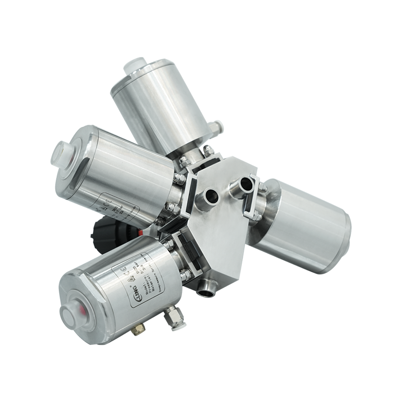
Filter-regulator installation in the air supply line provides localized air conditioning and pressure control specific to the valve actuator requirements, compensating for supply pressure variations and removing contaminants that might compromise actuator performance. Mount the filter-regulator assembly in an accessible location allowing convenient filter element replacement and condensate drainage without requiring extensive disassembly or interrupting operations on adjacent equipment. Orient the filter-regulator according to manufacturer instructions, typically vertically with the filter bowl downward to promote proper condensate drainage and contaminant settling. Adjust the regulator to deliver pressure approximately ten percent above the minimum actuator requirement, providing adequate operating margin while avoiding unnecessary actuator stress from excessive pressure.
Solenoid valve installation for automated valve control requires proper voltage verification, electrical connection integrity, and functional testing to ensure reliable valve actuation in response to control signals. Verify that solenoid valve voltage ratings match available power supplies, confirming whether AC or DC voltage is required and that voltage magnitude falls within acceptable ranges. Mount solenoid valves in orientations recommended by manufacturers, typically with coils upward to prevent moisture accumulation and allow proper venting. Electrical connections should utilize appropriate conduit, cable glands, or cord grips that maintain environmental protection ratings while providing strain relief preventing wire damage from vibration or inadvertent pulling forces.
Valve position indicators or limit switches provide feedback confirming valve position for control system monitoring and interlock functions, requiring proper mounting, adjustment, and verification during commissioning. Mechanical limit switches typically mount to the actuator using brackets that position switch actuators to engage cams or targets attached to the actuator stem, creating definitive position signals at predetermined valve travel points. Adjust limit switches to trigger precisely at the desired valve positions, typically fully open and fully closed for two-position valves, then verify proper operation by manually stroking the valve through its full range while observing switch state changes. Electrical connections to limit switches require attention to wire routing, strain relief, and environmental protection appropriate for the installation location.
Pneumatic System Connection Configuration
| Component | Location | Purpose | Adjustment Required |
| Filter-regulator | Near valve location | Air conditioning and pressure control | Set to actuator requirement |
| Solenoid valve | Between regulator and actuator | Automated control actuation | None typically |
| Positioner | Mounted on actuator | Proportional control positioning | Calibration required |
| Manual operator | Attached to actuator | Emergency manual override | Verify engagement |
| Quick exhaust valve | At actuator port | Rapid valve closure | None |
Commissioning Procedures and Functional Testing
Initial stroke testing without process fluid verifies mechanical operation, actuator performance, and absence of binding or interference before introducing potentially hazardous materials into the system. Apply instrument air gradually while observing actuator movement, listening for unusual sounds indicating interference or misalignment, and verifying smooth travel through the complete range from fully closed to fully open positions. For spring-return actuators, verify proper fail-safe operation by removing air pressure and confirming the valve moves to its predetermined safe position within expected time frames. Repeat stroke testing multiple times to identify intermittent problems and ensure consistent, repeatable operation before proceeding to pressure testing.
Seat leakage testing determines valve shutoff capability, critical for applications requiring tight shutoff to prevent product waste, maintain process control, or ensure safety system reliability. Standard seat leakage testing involves pressurizing the valve from the upstream side with the valve closed, then measuring leakage flow or pressure decay on the downstream side over a specified time period. Test pressures typically equal maximum operating pressure or a specified percentage thereof, with acceptable leakage rates defined by application requirements and industry standards such as ANSI/FCI 70-2 which classifies valve shutoff capability across multiple classes ranging from Class I for general service to Class VI for minimal detectable leakage in critical applications.
Control system integration testing verifies proper valve response to control signals, confirms correct fail-safe operation, and validates interlock functions before placing the valve in normal service. For automated on-off valves, verify proper opening and closing in response to solenoid valve energization, checking operation speed and confirming complete travel to fully open and fully closed positions. Proportional control valves require calibration of positioners or current-to-pressure converters, adjusting zero and span settings until valve position accurately tracks the control signal throughout the operating range. Test interlock functions by simulating upset conditions that should trigger valve closure, verifying that the valve responds appropriately and within required time frames to prevent process excursions or safety system failures.
Common Installation Problems and Corrective Actions
Actuator binding or sluggish operation typically indicates misalignment between the actuator stem and valve compressor, contamination in actuator chambers, or insufficient air pressure to overcome operating forces. Verify actuator mounting alignment by loosening mounting bolts slightly and checking whether operation improves, indicating that improper mounting created binding loads. Remove the actuator and inspect internal components for contamination, corrosion, or damage requiring cleaning or replacement. Measure actual air supply pressure at the actuator under operating conditions to identify pressure drops through undersized tubing, restrictive fittings, or inadequate filter-regulator capacity that prevents delivering required actuator pressure.
External leakage at valve body connections suggests improper gasket installation, insufficient bolt torque, damaged sealing surfaces, or incompatible gasket materials that have degraded upon contact with process fluids. Re-torque flange bolts using proper sequence and torque values, verifying uniform compression around the flange circumference. If leakage persists, disassemble the connection and inspect gasket condition, replacing damaged or degraded gaskets with appropriate materials confirmed compatible with the process fluid. Examine flange sealing surfaces for scratches, gouges, or warping that prevents proper gasket compression, refinishing or replacing damaged components as necessary to restore sealing capability.
Excessive seat leakage beyond acceptable limits indicates diaphragm damage, foreign material preventing complete closure, improper actuator sizing, or inadequate sealing force to overcome process pressure. Inspect the diaphragm for cuts, tears, or permanent deformation that prevents proper seating against the valve body. Remove any foreign material lodged in the seat area that prevents complete closure, examining upstream piping for debris sources requiring filtration or screening to prevent recurrence. Verify actuator sizing calculations confirming adequate force generation to compress the diaphragm against seat pressure, particularly for high-pressure applications or valves with large diaphragm areas requiring substantial closing force.
Documentation and Maintenance Planning
Comprehensive installation documentation provides essential information for troubleshooting, maintenance planning, and future modifications, including detailed records of valve specifications, installation configuration, and commissioning test results. Document valve tag numbers, sizes, pressure ratings, material construction, and specific model numbers for both valve bodies and actuators, creating cross-references to process and instrumentation diagrams and equipment databases. Photograph installed valves from multiple angles showing piping connections, actuator orientation, accessories, and clearances, providing visual records useful when planning maintenance activities or investigating operational problems remotely.
Preventive maintenance schedules should address diaphragm replacement intervals, actuator servicing requirements, air filter element changes, and periodic performance testing based on manufacturer recommendations and operational experience. Diaphragms represent the primary wear component in pneumatic diaphragm valves, requiring periodic replacement based on operating cycles, process fluid aggressiveness, and observed leakage or performance degradation. Actuator maintenance includes lubricating moving parts, inspecting seals and O-rings, and verifying spring tension in spring-return designs, with maintenance intervals ranging from annual inspections for light-duty applications to quarterly servicing for valves experiencing severe service conditions or critical applications intolerant of unplanned failures.
Spare parts inventory planning should include diaphragms sized for each valve installation, complete actuator rebuild kits, and commonly failed accessories such as solenoid valve coils, positioner components, and limit switches. Maintaining adequate spares minimizes downtime during corrective maintenance while enabling proactive replacement of wear components before failure disrupts operations. Consider maintaining complete spare valve assemblies for critical applications where extended downtime creates unacceptable production losses or safety risks, allowing rapid replacement of failed valves while repairs proceed offline without time pressure compromising quality.
Post-Installation Verification Steps
- Verify all bolted connections achieve specified torque values with proper tightening sequences documented and connection integrity confirmed through leak testing at operating pressure
- Confirm actuator stroke time meets specifications by measuring time required for complete travel from fully open to fully closed positions under normal operating conditions
- Document seat leakage test results comparing measured leakage rates against specified requirements and industry standards for the valve classification
- Test fail-safe operation by removing air pressure and verifying proper valve movement to predetermined safe position within required time frame without binding or hesitation
- Validate control system integration including signal response, position indication accuracy, and interlock function operation through comprehensive functional testing before normal operation begins
- Complete installation documentation including photographs, test records, configuration data, and maintenance requirements for incorporation into facility maintenance management systems


